
Page 403 - Cam Design Handbook
P. 403
THB12 9/19/03 7:34 PM Page 391
CAM SYSTEM DYNAMICS—ANALYSIS 391
50
40
30
20
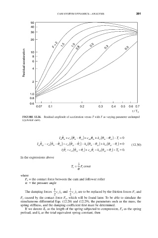
F = 2 1.5 1.0 0.8 0.5 0.3 0.0
Residual acceleration 8
10
6
4
2
1.0
0.8
0.6
0.07 0.1 0.2 0.3 0.4 0.5 0.6 0.7
t / T 1
FIGURE 12.24. Residual amplitude of acceleration versus T with F as varying parameter undamped
(cycloidal cam).
I q + ( ˙ q ˙ c q + ( q T = 0
˙
˙˙
k q - ) -
c q - ) +
m m sl m cp mb m s1 m cp i
c q - ) + (
˙
˙
˙˙
I q - ( ˙ q ˙ c q - ) - ( q k q - ) = 0
k q - )+ (
q
q
cp cp sl m cp s2 cp c sl m cp s2 cp c (12.30)
I q - ( ˙ cp q ˙ c c q - ( q - )+ T = . 0
˙ ˙
˙˙
c q - ) +
q
k
s2
0
cc c
cp
cc
s2
c
In the expressions above
y ˙˙
T = F cosa
o ˙ c
q
where
F n = the contact force between the cam and follower roller
a = the pressure angle
1 1
The damping forces cy ˙ 4 and cy ˙ 3 are to be replaced by the friction forces F 1 and
f
f
2 2
F 2 caused by the contact force F n, which will be found later. To be able to simulate the
simultaneous differential Eqs. (12.28) and (12.29), the parameters such as the mass, the
spring stiffness, and the damping coefficient first must be determined.
If we denote d rs as the length of the spring subjected to compression, F p as the spring
preload, and k t as the total equivalent spring constant, then