
Page 407 - Cam Design Handbook
P. 407
THB12 9/19/03 7:34 PM Page 395
CAM SYSTEM DYNAMICS—ANALYSIS 395
410
Flexibility and tolerance
Acceleration, m/sec. 2 205
0
–205
–410
0 120 240 360 480 600 720
Cam angle, deg.
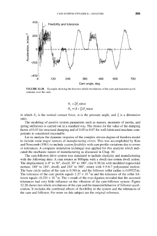
FIGURE 12.28. Example showing the first two whole revolutions of the cam and transient accel-
erations over the cam.
F
N = x sin a
n
1
N = ( 1+ F ) x sin a
2 n
in which F n is the normal contact force, a is the pressure angle, and x is a dimension
ratio.
The modeling of passive system parameters such as masses, moments of inertia, and
spring stiffnesses is carried out in a standard way. The choice for the value of the damping
factor of 0.03 for structural damping and of 0.05 to 0.07 for well-lubricated machine com-
ponents is considered reasonable.
Let us analyze the dynamic response of the complex eleven-degree-of freedom model
to include some major sources of manufacturing errors. This was accomplished by Kim
and Newcomb (1981) to include system flexibility with cam profile variations due to errors
or tolerances. A computer simulation technique was applied for this analysis which indi-
cated the stochastic nature of manufacturing as discussed in Chap. 10.
The cam-follower drive system was simulated to include elasticity and manufacturing
with the following data: A cam rotates at 800rpm with a dwell-rise-return dwell action.
The displacement is 0° to 30°, dwell; 30° to 180°, rise 0.381m with modified trapezoidal
motion; 180° to 210°, dwell; and 210° to 360°, return with 4-5-6-7 polynomial motion.
The base circle radius of the cam is 0.381m. and the follower roller radius is 0.09525m.
-5
The tolerance of the cam profile equals ±.27 ¥ 10 m and the tolerance of the roller fol-
-5
lower equals ±0.254 ¥ 10 m. The v-result of the eves figation revealed that the assumed
tolerances had very little influence on the vibration of the cam-follower system. Figure
12.28 shows two whole revolutions of the cam and the transient behavior of follower accel-
eration. It includes the combined effects of flexibility in the system and the tolerances of
the cam and follower. For more on this subject see the original reference.