
Page 395 - Cam Design Handbook
P. 395
THB12 9/19/03 7:34 PM Page 383
CAM SYSTEM DYNAMICS—ANALYSIS 383
Thus the return spring rate, the linear frequency ratio, and the maximum reflected
inertia ratio are
()
am . 15 50 2
¥
k = x¢¢ q ˙ 2 i = ( . 0051 36 ) = . 0257 10 6 N m
)( .65
r
max
h . 002
p
Ê ˆ 2
w b k b 2 k Ë ¯ 10 000
,
2
h = l i = i = = 931
.
˙
.
.
w 2 pq ˙ i I (2 pq ) 2 I (2 p ¥ 36 65 ) 2 0 005
b
i
m 2 50 2
6 50
Q = ( x¢ ) = ( . 00255 ) = . .
m
max
I . 0 005
From Fig. 12.11 we obtain b m = 0.006. The corresponding maximum driveshaft windup is
p
Ê ˆ
.
q - q = 0 006 Ë ¯ = 0 0094 rad (0 54. ∞)
.
i
c
2
and the associated dynamic windup torque is
p
.
k
T = bb =10 000 ¥ 0 006 = 94 2 N-m.
,
.
m s m
2
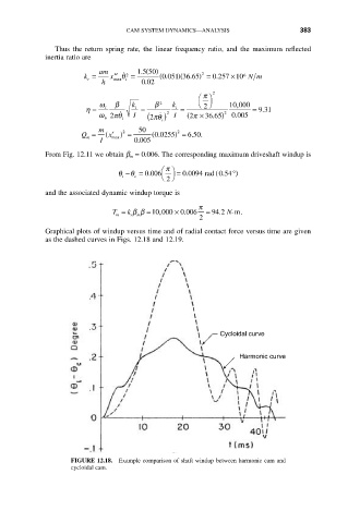
Graphical plots of windup versus time and of radial contact force versus time are given
as the dashed curves in Figs. 12.18 and 12.19.
Cycloidal curve
Harmonic curve
FIGURE 12.18. Example comparison of shaft windup between harmonic cam and
cycloidal cam.