
Page 394 - Cam Design Handbook
P. 394
THB12 9/19/03 7:34 PM Page 382
382 CAM DESIGN HANDBOOK
40
g m
m
b = .05 25 Q = 50
m
30
10
20
1 5
10
.1
0
0 5 10 15 20
h
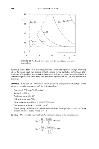
FIGURE 12.17. Radial force ratio chart for closed-track cam with a
cycloidal rise.
frequency ratios. Thus for a well-designed cam system that operates at high frequency
ratios, the closed-track cam system without a return spring has better performance char-
acteristics. Comparisons are academic because closed-track systems are utilized only in
commercial production machinery, and open-track systems are best for only the automo-
tive field.
EXAMPLE Consider an open-track dwell-rise-dwell cam-follower-driveshaft system
having a cycloidal cam curve with the following data:
Cam speed, 350rpm (36.65 rad/sec)
Stroke, h = 0.02m
Total cam angle, b = 90°
Follower mass, m = 50kg
Drive train spring stiffness, k s = 10,000N-m/rad
Cam moment of inertia, I = 0.005kg-m 2
Return spring coefficient (the ratio between the maximum spring force and maximum
nominal follower inertia force), a = 1.5
Solution The cycloidal cam study of the torsional windup of the system gives
2 h 2 ( .0 02 )
¢ x = = = . 00255
max
b p
2
2p h 2p ( . 0 02 )
x ¢¢ = = 2 = . 0051 .
max
b 2 Ê ˆ
p
Ë ¯
2