
Page 396 - Cam Design Handbook
P. 396
THB12 9/19/03 7:34 PM Page 384
384 CAM DESIGN HANDBOOK
5
Cycloidal
4 curve
F v (k N.) 3
Harmonic
curve
2
1
0
10 20 30 40
t (ms)
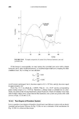
FIGURE 12.19. Example comparison of contact force between harmonic cam and
cycloidal cam.
If this design is unacceptable, we may replace the cycloidal cam curve with a simple
harmonic curve, other modified harmonic, or modified trapezoidal curve, keeping the other
condition intact. By so doing we can calculate
hp
¢ x = = . 002
max
2 b
hp 2
004
¢¢ =
x max = ..
2 b 2
6
h will remain unchanged, but k r becomes equal to 0.2 ¥ 10 N/m, and Q m becomes equal
to approximately 4.0.
From Fig. 12.11 we obtain b m = 0.0025. Thus q t - q c = 0.25° and its corresponding
peak windup torque is T m = 45N-m. Therefore, a change from a cycloidal rise to a har-
monic rise reduces the forcing function by about 50 percent. Charts of windup versus time
and of radial contact force versus time for this harmonic cam system are given as the solid
curves in Figs. 12.18 and 12.19.
12.4.3 Two-Degree-of-Freedom System
Let us consider a two-degree-of-freedom closed-track cam follower system with an elastic
camshaft and an elastic follower. In Fig. 12.20a we see a schematic of the mechanism. In
Fig. 12.20b it is observed that torque