
Page 417 - Cam Design Handbook
P. 417
THB13 9/19/03 7:56 PM Page 405
CAM SYSTEM DYNAMICS—RESPONSE 405
3-4-5 Polynomial
4.0 Gutman F-3
Modified trapezoidal
Freudenstein 1-3-5 harmonic
3.5
Normalized first peak of residual acceleration response 3.0 Freudenstein Berzak-Freudenstein 3-4-5-6-7
1-3 harmonic
Polynomial-D curve
Berzak-Freudenstein 3-4-5-6-7
Polynomial-E curve
Cycloidal
Modified sine
2.5
11th-degree polynomial
4-5-6-7 Polynomial
Modified trapezoidal
2.0
1.5
0.5 1.0 1.5 2.0 2.5
T1/ T N
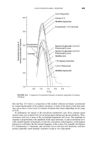
FIGURE 13.4. Comparison of normalized first-peak acceleration magnitudes for primary
vibrations.
files and Fig. 13.5 shows a comparison of the residual vibration envelopes (constructed
by connecting the peaks of the residual vibrations). A study of the figures yields that some
cam curves have a lower level of residual vibrations than others depending on the range
of T 1/T N.
In summation, the speeds of all cam-driven mechanisms vary. Even constant speed
systems must vary in speed from zero to design speed during start-up and shutdown. Thus,
resonances with one or more of the excitational frequencies will occur. The amplitude of
response is proportional to the amplitude of the input harmonic. A cam acceleration curve
with a limited number of harmonics avoids this coincidence if the frequency of the highest
harmonic is well below the first natural frequency of the system. For example, the Gutman
F-3, Freudenstein 1-3 harmonic, and cycloidal curves each have few harmonics and thus
produce generally sound dynamic responses except at very high speeds.