
Page 418 - Cam Design Handbook
P. 418
THB13 9/19/03 7:56 PM Page 406
406 CAM DESIGN HANDBOOK
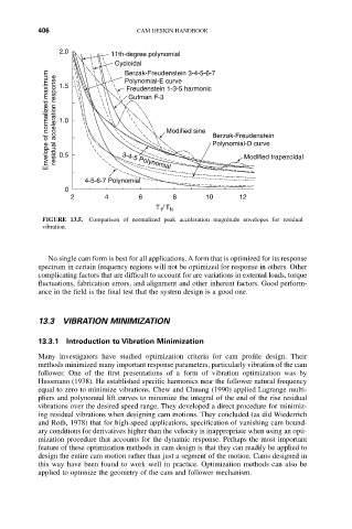
2.0 11th-degree polynomial
Cycloidal
Berzak-Freudenstein 3-4-5-6-7
Envelope of normalized maximum residual acceleration response 1.0 Gutman F-3 Modified sine Berzak-Freudenstein
Polynomial-E curve
1.5
Freudenstein 1-3-5 harmonic
Polynomial-D curve
0.5
3-4-5 Polynomial
4-5-6-7 Polynomial Modified trapezoidal
0
2 4 6 8 10 12
T / T N
1
FIGURE 13.5. Comparison of normalized peak acceleration magnitude envelopes for residual
vibration.
No single cam form is best for all applications. A form that is optimized for its response
spectrum in certain frequency regions will not be optimized for response in others. Other
complicating factors that are difficult to account for are variations in external loads, torque
fluctuations, fabrication errors, and alignment and other inherent factors. Good perform-
ance in the field is the final test that the system design is a good one.
13.3 VIBRATION MINIMIZATION
13.3.1 Introduction to Vibration Minimization
Many investigators have studied optimization criteria for cam profile design. Their
methods minimized many important response parameters, particularly vibration of the cam
follower. One of the first presentations of a form of vibration optimization was by
Hussmann (1938). He established specific harmonics near the follower natural frequency
equal to zero to minimize vibrations. Chew and Chuang (1990) applied Lagrange multi-
pliers and polynomial lift curves to minimize the integral of the end of the rise residual
vibrations over the desired speed range. They developed a direct procedure for minimiz-
ing residual vibrations when designing cam motions. They concluded (as did Wiederrich
and Roth, 1978) that for high-speed applications, specification of vanishing cam bound-
ary conditions for derivatives higher than the velocity is inappropriate when using an opti-
mization procedure that accounts for the dynamic response. Perhaps the most important
feature of these optimization methods in cam design is that they can readily be applied to
design the entire cam motion rather than just a segment of the motion. Cams designed in
this way have been found to work well in practice. Optimization methods can also be
applied to optimize the geometry of the cam and follower mechanism.