
Page 152 - Carbon Nanotube Fibres and Yarns
P. 152
Carbon nanotube yarn structures and properties 145
(A) (B)
0.8 1
0.7 0.9
0.8
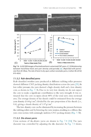
Yarn density (g/cm 3 ) 0.5 Yarn porosity 0.7 Twisted
0.6
0.6
0.5
0.4
0.4
0.3
0.3
0.2
Trend-twisted
0.1
Trend-twist-untwisted
0.1 0.2 Twist-untwisted
0
0 0 5000 10,000 15,000 20,000 25,000
0 5000 10,000 15,000 20,000 25,000
(C) Twist or false twist (T/m) (D) Twist or false twist (T/m)
Fig. 7.6 (A, B) SEM images of twisted and twist-untwisted CNT yarns. (C, D) Relationship
between twist/false twist and yarn density and porosity [6]. (Reprinted with permis-
sion from M. Miao, The role of twist in dry spun carbon nanotube yarns, Carbon 96 (2016)
819–826.)
7.1.3.2 Rub-densified yarns
Rub-densified twistless yarn produced at different rubbing roller pressures
showed different CNT packing density distributions across the yarn [29]. At
low roller pressure, the yarn showed a high-density shell and a low-density
core, as shown in Fig. 7.7A. Due to its very low density, we do not expect
the core to make a significant contribution to the yarn strength. It was es-
timated that the core occupies about 40% of the total yarn cross-sectional
area. The average density of the sheath could be estimated from the average
3
yarn density (0.64 g/cm ) divided by the area proportion of the sheath (i.e.,
3
0.6), giving a sheath density of 1.07 g/cm .
The low-density core can be eliminated by increasing the pressure between
the rubbing rollers and by lowering the yarn tension, resulting in a ribbon-like
yarn cross section with seemingly uniform CNT packing density (Fig. 7.7B).
7.1.3.3 Die-drawn yarns
Cross sections of die-drawn yarns are shown in Fig. 7.8 [30]. The yarn
diameter was controlled by adjusting the die diameter. As Fig. 7.9 shows,