
Page 21 - Carbon Nanotube Fibres and Yarns
P. 21
14 Carbon Nanotube Fibers and Yarns
with tuneable tube diameter, number of walls, length, alignment, covering
areas, growth rate, etc. Growth enhancers (oxygen-containing molecules,
e.g., water, alcohols, ethers, esters, ketones, aldehydes, and carbon dioxide)
have been used to dramatically increase the growth efficiency, tube length,
and alignment [4, 5].
Bedewy et al. [6] proposed a collective growth mechanism of vertically
aligned CNT forests. The CNT forest growth starts with the formation of
a thin “crust” of randomly oriented CNTs that resides on the top of the
forest after alignment emerges. They postulated that the abrupt termination
of CNT forest growth was caused by loss of the self-supporting structure.
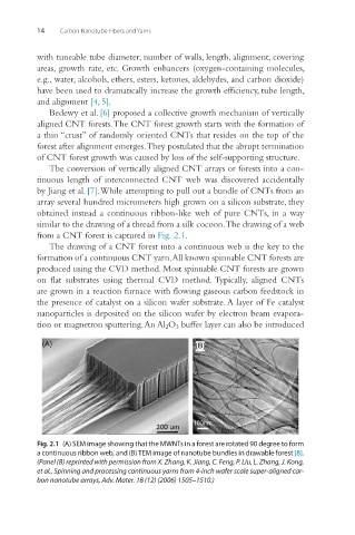
The conversion of vertically aligned CNT arrays or forests into a con-
tinuous length of interconnected CNT web was discovered accidentally
by Jiang et al. [7]. While attempting to pull out a bundle of CNTs from an
array several hundred micrometers high grown on a silicon substrate, they
obtained instead a continuous ribbon-like web of pure CNTs, in a way
similar to the drawing of a thread from a silk cocoon. The drawing of a web
from a CNT forest is captured in Fig. 2.1.
The drawing of a CNT forest into a continuous web is the key to the
formation of a continuous CNT yarn. All known spinnable CNT forests are
produced using the CVD method. Most spinnable CNT forests are grown
on flat substrates using thermal CVD method. Typically, aligned CNTs
are grown in a reaction furnace with flowing gaseous carbon feedstock in
the presence of catalyst on a silicon wafer substrate. A layer of Fe catalyst
nanoparticles is deposited on the silicon wafer by electron beam evapora-
tion or magnetron sputtering. An Al 2 O 3 buffer layer can also be introduced
Fig. 2.1 (A) SEM image showing that the MWNTs in a forest are rotated 90 degree to form
a continuous ribbon web, and (B) TEM image of nanotube bundles in drawable forest [8].
(Panel (B) reprinted with permission from X. Zhang, K. Jiang, C. Feng, P. Liu, L. Zhang, J. Kong,
et al., Spinning and processing continuous yarns from 4-inch wafer scale super-aligned car-
bon nanotube arrays, Adv. Mater. 18 (12) (2006) 1505–1510.)