
Page 12 - Carbon Nanotubes
P. 12
2 M. ENDO et al.
Fig. 1. Comparative preparation methods for micrometer
size fibrous carbon and carbon nanotubes as one-dimensional
forms of carbon.
methods give similar structures, in which ultra-fine
catalytic particles are encapsulated in the tubule tips
(Fig. 2). Continued pyrolytic deposition occurs on the
initially formed thin carbon fibers causing thickening
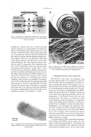
(ca. 10 pm diameter, Fig. 3a). Substrate catalyzed fi-
bers tend to be thicker and the floating technique pro-
duces thinner fibers (ca. 1 pm diameter). This is due
to the shorter reaction time that occurs in the fluid-
ized method (Fig. 3b). Later floating catalytic meth-
ods are useful for large-scale fiber production and,
thus, VGCFs should offer a most cost-effective means Fig. 3. Vapor-grown carbon fibers obtained by substrate
of producing discontinuous carbon fibers. These method with diameter ca. 10 pm (a) and those by floating cat-
VGCFs offer great promise as valuable functional car- alyst method (b) (inserted, low magnification).
bon filler materials and should also be useful in car-
bon fiber-reinforced plastic (CFRP) production. As
seen in Fig. 3b even in the “as-grown” state, carbon 3. PREPARATION OF VGCFs AND PCNTs
particles are eliminated by controlling the reaction
conditions. This promises the possibility of producing The PCNTs in this study were prepared using
pure ACNTs without the need for separating spheroidal the same apparatus[9] as that employed to produce
carbon particles. Hitherto, large amounts of carbon VGCFs by the substrate method[l0,15]. Benzene va-
particles have always been a byproduct of nanotube por was introduced, together with hydrogen, into a ce-
production and, so far, they have only been eliminated ramic reaction tube in which the substrate consisted
by selective oxidation[l4]. This has led to the loss of of a centrally placed artificial graphite rod. The tem-
significant amounts of nanotubes - ca. 99%. perature of the furnace was maintained in the 1000°C
range. The partial pressure of benzene was adjusted
to be much lower than that generally used for the
preparation of VGCFs[lO,lS] and, after one hour
decomposition, the furnace was allowed to attain
room temperature and the hydrogen was replaced by
argon. After taking out the substrate, its surface was
scratched with a toothpick to collect the minute fibers.
Subsequently, the nanotubes and nanoscale fibers
were heat treated in a carbon resistance furnace un-
der argon at temperatures in the range 2500-3000°C
for ca. 10-15 minutes. These as-grown and sequen-
tially heat-treated PCNTs were set on an electron mi-
croscope grid for observation directly by HRTEM at
400kV acceleration voltage.
It has been observed that occasionally nanometer
scale VGCFs and PCNTs coexist during the early
stages of VGCF processing (Fig. 4). The former tend
Fig. 2. Vapour-grown carbon fiber showing relatively early
stage of growth; at the tip the seeded Fe catalytic particle is to have rather large hollow cores, thick tube walls and
encapsulated. well-organized graphite layers. On the other hand,