
Page 13 - Carbon Nanotubes
P. 13
Pyrolytic carbon nanotubes from vapor-grown carbon fibers 3
a t
b
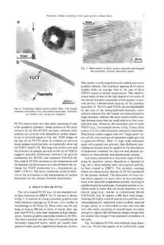
Fig. 5. Heat-treated pyrolytic carbon nanotube and enlarged
one (inserted), without deposited carbon.
This results in well-organized multi-walled concentric
graphite tubules. The interlayer spacing (0.34 nm) is
slightly wider on average than in the case of thick
VGCFs treated at similar temperatures. This small in-
crease might be due to the high degree of curvature of
the narrow diameter nanotubes which appears to pre-
vent perfect 3-dimensional stacking of the graphitic
layers[ 16,171. PCNTs and VGCFs are distinguishable
Fig. 4. Coexisting vapour-grown carbon fiber, with thicker by the sizes of the well-graphitized domains; cross-
diameter and hollow core, and carbon nanotubes, with thin-
ner hollow core, (as-grown samples). sections indicate that the former are characterized by
single domains, whereas the latter tend to exhibit mul-
tiple domain areas that are small relative to this cross-
PCNTs tend to have very thin walls consisting of only sectional area. However, the innermost part of some
a few graphitic cylinders. Some sections of the outer VGCFs (e.g., the example shown in Fig. 5) may often
surfaces of the thin PCNTs are bare, whereas other consist of a few well-structured concentric nanotubes.
sections are covered with amorphous carbon depos- Theoretical studies suggest that this “single grain” as-
its (as is arrowed region in Fig. 4a). TEM images of pect of the cross-sections of nanotubes might give rise
the tips of the PCNTs show no evidence of electron to quantum effects. Thus, if large scale real-space
beam opaque metal particles as is generally observed super-cell concepts are relevant, then Brillouin zone-
for VGCF tips[lO,l5]. The large size of the cores and foiding techniques may be applied to the description
the presence of opaque particles at the tip of VGCFs of dispersion relations for electron and phonon dy-
suggests possible differences between the growth namics in these pseudo one-dimensional systems.
mechanism for PCNTs and standard VGCFs[7-91. A primary nanotube at a very early stage of thick-
The yield of PCNTs increases as the temperature and ening by pyrolytic carbon deposition is depicted in
the benzene partial pressure are reduced below the op- Figs. 6a-c; these samples were: (a) as-grown and (b),
timum for VGCF production (i.e., temperature ca. (c) heat treated at 2500°C. The pyrolytic coatings
1000°-11500C). The latter conditions could be effec- shown are characteristic features of PCNTs produced
tive in the prevention or the minimization of carbon by the present method. The deposition of extra car-
deposition on the primary formed nanotubules. bon layers appears to occur more or less simultane-
ously with nanotube longitudinal growth, resulting in
spindle-shaped morphologies. Extended periods of py-
4. STRUCTURES OF PCNTs
rolysis result in tubes that can attain diameters in the
Part of a typical PCNT (ca. 2.4 nm diameter) af- micron range (e.g., similar to conventional (thick)
ter heat treatment at 2800°C for 15 minutes is shown VGCFs[lO]. Fig. 6c depicts a 002 dark-field image,
in Fig. 5. It consists of a long concentric graphite tube showing the highly ordered central core and the outer
with interlayer spacings ca. 0.34 nm-very similar in inhomogeneously deposited polycrystalline material
morphology to ACNTs[ 1,3]. These tubes may be very (bright spots). It is worthwhile to note that even the
long, as long as 100 nm or more. It would, thus, ap- very thin walls consisting of several layers are thick
pear that PCNTs, after heat treatment at high temper- enough to register 002 diffraction images though they
atures, become graphitic nanotubes similar to ACNTs. are weaker than images from deposited crystallites on
The heat treatment has the effect of crystallizing the the tube.
secondary deposited layers, which are usually com- Fig. 7a,b depicts PCNTs with relatively large diam-
posed of rather poorly organized turbostratic carbon. eters (ca. 10 nm) that appear to be sufficiently tough