
Page 14 - Carbon Nanotubes
P. 14
4 M. ENDO et al.
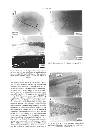
Fig. 7. Bent and twisted PCNT (heat treated at 2500T).
Fig. 6. PCNTs with partially deposited carbon layers (arrow
indicates the bare PCNT), (a) as-grown, (b) partially exposed
nanotube and (c) 002 dark-field image showing small crys-
tallites on the tube and wall of the tube heat treated at
2500°C.
and flexible to bend, twist, or kink without fractur-
ing. The basic structural features and the associated
mechanical behavior of the PCNTs are, thus, very dif-
ferent from those of conventional PAN-based fibers
as well as VGCFs, which tend to be fragile and easily
broken when bent or twisted. The bendings may occur
at propitious points in the graphene tube network[l8].
Fig. 8a,b shows two typical types of PCNT tip
morphologies. The caps and also intercompartment di-
aphragms occur at the tips. In general, these consist
of 2-3 concentric layers with average interlayer spac-
ing of ca. 0.38 nm. This spacing is somewhat larger
than that of the stackings along the radial direction,
presumably (as discussed previously) because of sharp
curvature effects. As indicated in Fig. 9, the conical
shapes have rather symmetric cone-like shells. The an-
gle, ca. 20°, is in good agreement with that expected
for a cone constructed from hexagonal graphene
sheets containing pentagonal disclinations -as is
Fig. 9e. Ge and Sattler[l9] have reported nanoscale
conical carbon materials with infrastructure explain-
able on the basis of fullerene concepts. STM measure- Fig. 8. The tip of PCNTs with continuous hollow core (a)
ments show that nanocones, made by deposition of and the cone-like shape (b) (T indicates the toroidal struc-
very hot carbon on HOPG surfaces, often tend to ture shown in detail in Fig. 11).