
Page 72 - Carbon Nanotubes
P. 72
Carbon nanotubes: I. Geometrical considerations 61
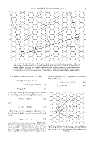
Fig. 4. Screw helicity: the system of (P, Q) coordinates used to describe the orientation of the two-
dimensional sp2 carbon layer in an unrolled cylindrical sheet whose edges are shown by the slanted un-
labelled full lines. Closure of the cylinder is obtained by rolling the sheet around the direction of the cylinder
axis given by the dotted line and superimposing hexagons A and B. The slanted dashed lines correspond
to a continuous line of unbroken hexagons of the cylinder, and indicate the apparent angle of pitch 0.
l.t is therefore possible to impose the limits: hence, assuming that is practically constant and
writing d for dj, j+L,
P I Pi I int[2arj/(3G/2)]
2~d nj,j+l (I)3G/2 (13)
=
(int = integral part of) (8) ni,j+l(I) = 10 (14)
Qj
Pi
0 I I (9)
in which Qi = 0 and Qi = Pi correspond to cases I and
I1 respectively, and for which eqn (4) becomes:
27rri(I) = Pi3G/2 (10)
and
2Tri(11) = P,&G. (1 1)
Referring now to the symmetric tubule, the inter-
layer distance dj, j+n between two layers of radii ri and
rj;-+n IS:
di,i+n = ri+n - Ti (12)
and, for two consecutive layers, df,j+l = 0.339 nm[5].
For the configuration of hexagons in case I, the in-
crease in length of the circumference of the (i + 1)th Fig. 5. Screw helicity: the three vectors corresponding to
=
(R/ Gd26, with P, = 5, Q, = 3 and P, = 4, Q, = 6 (see
laver with reswct to the circumference of the ith layer text). The vector (Pi, -Qi) characterizes the optical isomer
must be equal to an integral and even multiple of I x I ; of (Pi,Qd.