
Page 79 - Carbon Nanotubes
P. 79
68 K. SATTLER
*
4.00
3.00
2.00
1u.4
20.8
31.2 ns
1.00
Fig. 3. STM images of fullerene tubes on a graphite
substrate.
0
0 1.00 2.00 3.00 4,00
formed, further concentric shells can be added by gra- nu
phitic cylindrical layer growth.
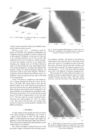
The c60+10i (j = 1,2,3, . . . ) tube has an outer di- Fig. 4. Atomic resolution STM image of a carbon tube, 35 A
in diameter. In addition to the atomic structure, a zigzag su-
ameter of 9.6 A[18]. In its armchair configuration, the perpattern along the tube axis can be seen.
hexagonal rings are arranged in a helical fashion with
a chiral angle of 30 degrees. In this case, the tube axis
is the five-fold symmetric axis of the C60-cap. The
single-shell tube can be treated as a rolled-up graph- fect graphitic cylinders. The bundle is disturbed in a
ite sheet that matches perfectly at the closure line. small region in the upper left part of the image. In the
Choosing the cylinder joint in different directions closer view in Fig. 6, we recognize six tubes at the bun-
leads to different helicities. One single helicity gives dle surface. The outer shell of each tube is broken, and
a set of discrete diameters. To obtain the diameter that an inner tube is exposed. We measure again an inter-
matches exactly the required interlayer spacing, the tube spacing of -3.4 A. This shows that the exposed
tube layers need to adjust their helicities. Therefore, inner tube is the adjacent concentric graphene shell.
in general, different helicities for different layers in a The fact that all the outer shells of the tubes in the
multilayer tube are expected. In fact, this is confirmed bundles are broken suggests that the tubes are strongly
by our experiment. coupled through the outer shells. The inner tubes,
In Fig. 4 we observe, in addition to the atomic lat- however, were not disturbed, which indicates that the
tice, a zigzag superpattern along the axis at the sur-
face of the tube. The zigzag angle is 120" and the
period is about 16 A. Such superstructure (giant lat-
tice) was found earlier for plane graphite[lO]. It is a
Moire electron state density lattice produced by dif-
ferent helicities of top shell and second shell of a tube.
The measured period of 16 A reveals that the second
layer of the tube is rotated relative to the first layer I
by 9". The first and the second cylindrical layers,
therefore, have chiral angles of 5" and -4", respec-
tively. This proves that the tubes are, indeed, com-
posed of at least two coaxial graphitic cylinders with I
different helicities.
5. BUNDLES D
In some regions of the samples the tubes are found
to be closely packed in bundles[20]. Fig. 5 shows a
-200 A broad bundle of tubes. Its total length is
2000 A, as determined from a larger scale image. The
diameters of the individual tubes range from 20-40 A. ....
They are perfectly aligned and closely packed over the Fig. 5. STM image of a long bundle of carbon nanotubes.
whole length of the bundle. The bundle is partially broken in a small area in the upper
Our atomic-resolution studies[ 101 did not reveal left part of the image. Single tubes on the flat graphite sur-
any steps or edges, which shows that the tubes are per- face are also displayed.