
Page 176 - Carrahers_Polymer_Chemistry,_Eighth_Edition
P. 176
Polycondensation Polymers 139
LC melts. Copolymerization with 4,4’-biphenol and terephthalic acid gives Ekkcel. Ekkcel does
melt before it decomposes. Certain forms can be compression molded and others injected molded.
Reaction of poly(1,4-benzoate) with PET gives a material that can be injected molded. These LCs
are chemical resistant, with high tensile strength. LC films with mesogenic side chains can be used
in information storage devices.
In general, because of the high order present in LCs, especially within their ordered state, they
have low void densities and as such exhibit good stability to most chemicals, including acids,
bleaches, common liquids, and so on; low gas permeability; relatively high densities; they are
strong and stiff with tensile moduli of the order of 10–25 GPs and tensile strengths in the range of
120–260 MPa.
Today, there exists a number of routes for processing that have been modifi ed for LC materials.
In general, they offer low shrinkage and warpage during molding, good repeatability from part to
part and low heats of fusion, allowing rapid melting and cooling during processing.
Their low melt viscosity permits molding of thin sections and complex shapes. Counter, their
tendency to form ordered structures causes LC materials to be particularly susceptible to molecular
orientation effects during processing.
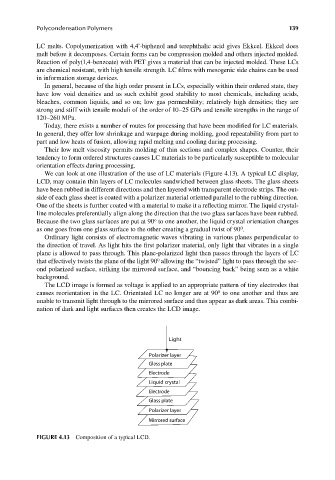
We can look at one illustration of the use of LC materials (Figure 4.13). A typical LC display,
LCD, may contain thin layers of LC molecules sandwiched between glass sheets. The glass sheets
have been rubbed in different directions and then layered with transparent electrode strips. The out-
side of each glass sheet is coated with a polarizer material oriented parallel to the rubbing direction.
One of the sheets is further coated with a material to make it a reflecting mirror. The liquid crystal-
line molecules preferentially align along the direction that the two glass surfaces have been rubbed.
o
Because the two glass surfaces are put at 90 to one another, the liquid crystal orientation changes
0
as one goes from one glass surface to the other creating a gradual twist of 90 .
Ordinary light consists of electromagnetic waves vibrating in various planes perpendicular to
the direction of travel. As light hits the first polarizer material, only light that vibrates in a single
plane is allowed to pass through. This plane-polarized light then passes through the layers of LC
0
that effectively twists the plane of the light 90 allowing the “twisted” light to pass through the sec-
ond polarized surface, striking the mirrored surface, and “bouncing back” being seen as a white
background.
The LCD image is formed as voltage is applied to an appropriate pattern of tiny electrodes that
0
causes reorientation in the LC. Orientated LC no longer are at 90 to one another and thus are
unable to transmit light through to the mirrored surface and thus appear as dark areas. This combi-
nation of dark and light surfaces then creates the LCD image.
Light
Polarizer layer
Glass plate
Electrode
Liquid crystal
Electrode
Glass plate
Polarizer layer
Mirrored surface
FIGURE 4.13 Composition of a typical LCD.
9/14/2010 3:38:37 PM
K10478.indb 139 9/14/2010 3:38:37 PM
K10478.indb 139