
Page 107 - Centrifugal Pumps Design and Application
P. 107
88 Centrifugal Pumps: Design and Application
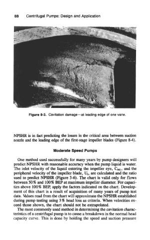
Figure 8-3. Cavitation damage—at leading edge of one vane.
NPSHR is in fact predicting the losses in the critical area between suction
nozzle and the leading edge of the first-stage impeller blades (Figure 84).
Moderate Speed Pumps
One method used successfully for many years by pump designers will
predict MPSHR with reasonable accuracy when the pump liquid is water.
The inlet velocity of the liquid entering the impeller eye, CMI» and the
peripheral velocity of the impeller blade, U t, are calculated and the ratio
used to predict NPSHR (Figure 3-6), The chart is valid only for flows
between 50% and 100% BEP at maximum impeller diameter. For capaci-
ties above 100% BEP, apply the factors indicated on the chart. Develop-
ment of this chart is a result of acquisition of many years of pump test
data. Values read from the chart will approximate the NPSHR established
during pump testing using 3 % head loss as criteria. When velocities ex-
ceed those shown, the chart should not be extrapolated.
The most commonly used method in determining the cavitation charac-
teristics of a centrifugal pump is to cause a breakdown in the normal head
capacity curve. This is done by holding the speed and suction pressure