
Page 113 - Centrifugal Pumps Design and Application
P. 113
94 Centrifugal Pumps: Design and Application
Both the friction losses and the acceleration losses are proportional to
the square of the liquid velocity as it approaches the impeller eye with a
constant of proportionality designated by Kj. The losses due to blade en-
try are proportional to the square of the velocity of flow relative to the
blade leading edge with a constant of proportionality designated by K 2.
To prevent cavitation, these losses must be compensated by supplying ad-
equate NPSH to the pump. This "cavitation-free" NPSHR can then be
expressed as:
2
where the first term, K}C Mi /2g, represents the friction and acceleration
2
losses, and the second term, K/zW /2g, represents the blade entry losses,
From this, it can be seen that, in small pumps of low speed, the first term
is predominant, while for large and/or high speed pumps, the second
term is the controlling factor and the first term is of secondary impor-
tance. This explains why it is often possible to reduce NPSHR on moder-
ate speed pumps by changing to a larger eye impeller. As cavitation is
most likely to occur in the region where the relative velocity, w, is high-
est, the calculation is based only on the maximum diameter of the blade
tip, D,, at the impeller entry.
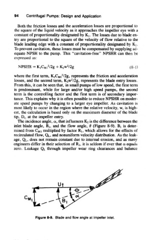
The incidence angle, a, that influences Ka is the difference between the
inlet blade angle, Bj, and the flow angle, 0 (Figure 8-9). Bj is deter-
mined from CMI multiplied by factor Rj, which allows for the effects of
recirculated flow, Q L, and nonuniform velocity distribution. As the leak-
age, Q L, does not remain constant due to internal erosion, and as many
engineers differ in their selection of RI, it is seldom if ever that a equals
zero. Leakage QL through impeller wear ring clearances and balance
Figure 8-9. Blade and flow angle at impeller inlet.