
Page 114 - Centrifugal Pumps Design and Application
P. 114
NPSH 95
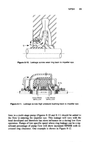
Figure 8-10. Leakage across wear ring back to impeller eye.
Figure 8-11. Leakage across high pressure bushing back to impeller eye.
lines in a multi-stage pump (Figures 8-10 and 8-11) should be added to
the flow Q entering the impeller eye. This leakage will vary with the
head developed and therefore has more influence on a during low flow
operation. Pumps of low specific speed where ring leakage can be a sig-
nificant percentage of pump flow will show increased NPSHR with in-
creased ring clearance. One example is shown in Figure 8-12.