
Page 185 - Centrifugal Pumps Design and Application
P. 185
160 Centrifugal Pumps: Design and Application
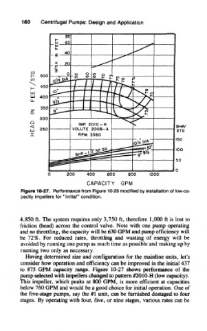
Figure 10-27. Performance from Figure 10-25 modified by installation of low-ca-
pacity impellers for "initial" condition,
4,850 ft. The system requires only 3,750 ft, therefore 1,000 ft is lost to
friction (head) across the control valve. Note with one pump operating
and no throttling, the capacity will be 630 GPM and pump efficiency will
be 72%. For reduced rates, throttling and wasting of energy will be
avoided by running one pump as much time as possible and making up by
running two only as necessary.
Having determined size and configuration for the mainline units, let's
consider how operation and efficiency can be improved in the initial 437
to 875 GPM capacity range. Figure 10-27 shows performance of the
pump selected with impellers changed to pattern #2010-H (low capacity).
This impeller, which peaks at 800 GPM, is more efficient at capacities
below 760 GPM and would be a good choice for initial operation. One of
the five-stage pumps, say the #1 unit, can be furnished destaged to four
stages. By operating with four, five, or nine stages, various rates can be