
Page 186 - Centrifugal Pumps Design and Application
P. 186
Pipeline, Waterflood and CO 2 Pumps 161
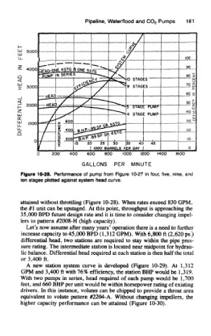
Figure 10-28. Performance of pump from Figure 10-27 in four, five, nine, and
ten stages plotted against system head curve.
attained without throttling (Figure 10-28). When rates exceed 830 GPM,
the #1 unit can be upstaged. At this point, throughput is approaching the
35,OCX) BPD future design rate and it is time to consider changing impel-
lers to pattern #2008-H (high capacity).
Let's now assume after many years' operation there is a need to further
increase capacity to 45,000 BPD (1,312 GPM). With 6,800 ft (2,620 psi)
differential head, two stations are required to stay within the pipe pres-
sure rating. The intermediate station is located near midpoint for hydrau-
lic balance. Differential head required at each station is then half the total
or 3,400 ft.
A new station system curve is developed (Figure 10-29). At 1,312
GPM and 3,400 ft with 76% efficiency, the station BMP would be 1,319.
With two pumps in series, head required of each pump would be 1,700
feet, and 660 BHP per unit would be within horsepower rating of existing
drivers. In this instance, volutes can be chipped to provide a throat area
equivalent to volute pattern #2204-A. Without changing impellers, the
higher capacity performance can be attained (Figure 10-30).