
Page 188 - Centrifugal Pumps Design and Application
P. 188
Pipeline, Waterflood and COa Pumps 163
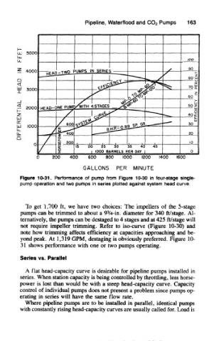
Figure 10-31. Performance of pump from Figure 10-30 in four-stage single
pump operation and two pumps in series plotted against system head curve
To get 1,700 ft, we have two choices: The impellers of the 5-stage
3
pumps can be trimmed to about a 9 /4-in. diameter for 340 ft/stage. Al-
ternatively, the pumps can be destaged to 4 stages and at 425 ft/stage will
not require impeller trimming. Refer to iso-curve (Figure 10-30) and
note how trimming affects efficiency at capacities approaching and be-
yond peak. At 1,319 GPM, destaging is obviously preferred. Figure 10-
31 shows performance with one or two pumps operating.
Series vs. Parallel
A flat head-capacity curve is desirable for pipeline pumps installed in
series. When station capacity is being controlled by throttling, less horse-
power is lost than would be with a steep head-capacity curve. Capacity
control of individual pumps does not present a problem since pumps op-
erating in series will have the same flow rate.
Where pipeline pumps are to be installed in parallel, identical pumps
with constantly rising head-capacity curves are usually called for. Load is