
Page 223 - Centrifugal Pumps Design and Application
P. 223
High Speed Pumps 19?
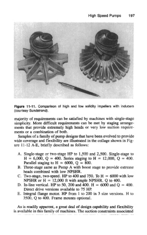
Figure 11-11. Comparison of high and low solidity impellers with inducers
(courtesy Sundstrand).
majority of requirements can be satisfied by machines with single-stage
simplicity. More difficult requirements can be met by staging arrange-
ments that provide extremely high heads or very low suction require-
ments or a combination of both.
Samples of a family of pump designs that have been evolved to provide
wide coverage and flexibility are illustrated in the collage shown in Fig-
ure 11-12 A-E, briefly described as follows:
A. Single-stage or two-stage HP to 1,500 and 2,500. Single-stage to
H = 6,000, Q = 400. Series staging to H = 12,000, Q = 400.
Parallel staging to H = 6000, Q - 800.
B. Three-stage same as Pump A with boost stage to provide extreme
heads combined with low NPSHR.
C. Two-stage, two-speed. HP to 400 and 750. To H = 6000 with low
NPSHR or H = 12,000 ft with ample NPSHR. Q to 400.
D. In-line vertical. HP to 50, 200 and 400. H = 6000 and Q = 400,
Direct drive versions available to 75 HP.
E. Integral flange motor. HP from 1 to 200 in 3 size versions. H to
3500, Q to 400. Frame mounts optional.
As is readily apparent, a great deal of design capability and flexibility
is available in this family of machines. The suction constraints associated