
Page 86 - Centrifugal Pumps Design and Application
P. 86
68 Centrifugal Pumps: Design and Application
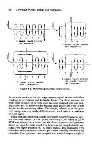
Figure 6-2. Multi-stage pump stage arrangements.
throat to the suction of the next stage imparts a spiral motion to the flow
resulting in prerotation and hydraulic losses. For these reasons, the
multi-stage pumps of 25 or more years ago were designed with high loop-
ing crossovers. To achieve radial balance these crossovers were in both
the top and bottom casing halves. This design, referred to as the "pret-
zel" casing, was very costly, difficult to cast, and limited to a maximum
of eight stages.
These problems prompted a study to evaluate the performance of vari-
ous crossover shapes. A 4-in. pump delivering 1,200 GPM at 3,550
RPM was selected as a model and the three crossover configurations
shown in Figure 6-3 were tested. For these tests the pump hydraulic pas-
sages were highly polished (60-80 micro-inches), ring clearances were
minimized and component crossover parts were carefully matched using
a template. Configuration 1 was designed with a total divergence angle of