
Page 87 - Centrifugal Pumps Design and Application
P. 87
Design of Multi-Stage Casing 69
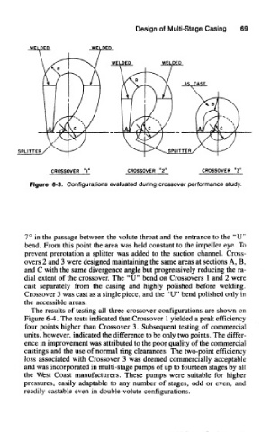
Figure 6-3. Configurations evaluated during crossover performance study.
7° in the passage between the volute throat and the entrance to the "U"
bend. From this point the area was held constant to the impeller eye. To
prevent prerotation a splitter was added to the suction channel. Cross-
overs 2 and 3 were designed maintaining the same areas at sections A, B,
and C with the same divergence angle but progressively reducing the ra-
dial extent of the crossover. The "U" bend on Crossovers 1 and 2 were
cast separately from the casing and highly polished before welding.
Crossover 3 was cast as a single piece, and the "U" bend polished only in
the accessible areas.
The results of testing all three crossover configurations are shown on
Figure 6-4. The tests indicated that Crossover 1 yielded a peak efficiency
four points higher than Crossover 3. Subsequent testing of commercial
units, however, indicated the difference to be only two points. The differ-
ence in improvement was attributed to the poor quality of the commercial
castings and the use of normal ring clearances. The two-point efficiency
loss associated with Crossover 3 was deemed commercially acceptable
and was incorporated in multi-stage pumps of up to fourteen stages by all
the West Coast manufacturers. These pumps were suitable for higher
pressures, easily adaptable to any number of stages, odd or even, and
readily castable even in double-volute configurations.