
Page 91 - Centrifugal Pumps Design and Application
P. 91
Design of Multi-Stage Casing 73
section. For additional stages, the sections are duplicated in plastic mate-
rial. For each stage combination, plastic sections should be assembled on
their own mounting boards, This arrangement will allow several pumps
of different stages to be produced at the same time.
Foundries
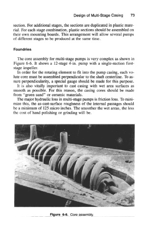
The core assembly for multi-stage pumps is very complex as shown in
Figure 6-6. It shows a 12-stage 4-in. pump with a single-suction first-
stage impeller.
In order for the rotating element to fit into the pump casing, each vo-
lute core must be assembled perpendicular to the shaft centerline. To as-
sure perpendicularity, a special gauge should be made for this purpose.
It is also vitally important to cast casing with wet area surfaces as
smooth as possible. For this reason, the casing cores should be made
from "green sand" or ceramic materials.
The major hydraulic loss in multi-stage pumps is friction loss. To mini-
mize this, the as-cast-surface roughness of the internal passages should
be a minimum of 125 micro inches. The smoother the wet areas, the less
the cost of hand polishing or grinding will be.
Figure 6-6. Core assembly.