
Page 358 - Challenges in Corrosion Costs Causes Consequences and Control(2015)
P. 358
336 CONSEQUENCES OF CORROSION
Pits
Bottom
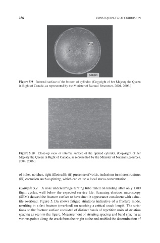
Figure 5.9 Internal surface of the bottom of cylinder. (Copyright of her Majesty the Queen
in Right of Canada, as represented by the Minister of Natural Resources, 2004, 2006.)
Figure 5.10 Close-up view of internal surface of the opened cylinder. (Copyright of her
Majesty the Queen in Right of Canada, as represented by the Minister of Natural Resources,
2004, 2006.)
of holes, notches, tight fillet radii; (ii) presence of voids, inclusions in microstructure;
(iii) corrosion such as pitting, which can cause a local stress concentration.
Example 5.1 A nose undercarriage turning tube failed on landing after only 1300
flight cycles, well below the expected service life. Scanning electron microscopy
(SEM) showed the fracture surface to have ductile appearance consistent with a duc-
tile overload. Figure 5.13a shows fatigue striations indicative of a fracture mode,
resulting in a fast fracture (overload) on reaching a critical crack length. The stria-
tions on the fracture surface consisted of distinct bands of repetitive units of striation
spacing as seen in the figure. Measurement of striating spacing and band spacing at
various points along the crack from the origin to the end enabled the determination of