
Page 123 - Chemical Process Equipment - Selection and Design
P. 123
6.3. LIQUIDS 95
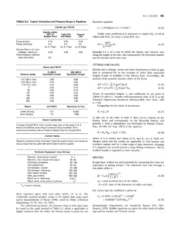
.2. Typical Velocities and Pressure Drops in Pipelines Karman’s equation
Liquids (psiJ100ft) f = 1.3251[ln(D/~) + 1.3123)]-’. (6.23)
Liquids within
50°F of Light Oils Viscous Under some conditions it is necessary to employ Eq. (6.18) in
Bubble Point and Water Oils differential form. In terms of mass flow rate.
Pump suction 0.15 0,25 0.25 8m2f
Pump discharge 2.0 2.0 2.0 dP =- (6.24)
(or 5-7 fps) (or 5-7 fps) (or 3-4 ips) gcn2pD5 dL’
Gravity flow to or from
tankage. maximurn 0.05 0.05 0.05 Example 6.4 is of a case in which the density and viscosity vary
Thermosyphon reboiler along the length of the line, and consequently the Reynolds number
inlet and outlet 0.2 and the friction factor also vary.
FllTlNGS AND VALVES
Gases (psi / 100 ft!
Friction due to fittings, valves and other disturbances of flow in pipe
0-300 ft 300-600 ft lines is accounted for by the concepts of either their equivalent
Pressure (psig) Equivalent Length Equivalent Length
lengths of pipe or multiples of the velocity head. Accordingly, the
~ ~
-73.7 (28in.Vac3 0.06 0.03 pressure drop equation assumes either of the forms
-12.2 (25 in. Vac) 0.15 0.05
-7.5(15in.Vac3 0.15 0.08 (6.25)
0 0.25 0.13 (6.26)
50 0.35 0.1 8
a 00 0.50 0.25 Values of equivalent lengths L, and coefficients Ki are given in
150 0.60 0.30 Tables 6.4 and 6.5. Another well-documented table of Ki is in the
200 0.70 0.35
500 2.05 1 .oo Chemical Engineering Handbook (McGraw-Hill, New York, 1984
p. 5.38).
Steam psi/ 100 ft Maximum ftJmin Comparing the two kinds of parameters,
Under 50 psig 0.4 10,000 Ki = fLi/D (6.27)
Over 50 psig 1 .0 7000
so that one or the other or both of these factors depend on the
Steam Condensate friction factor and consequently on the Reynolds number and
possibly E. Such a dependence was developed by Hooper [Chem.
To traps, 0.2 psi/105 ft. From bucket traps, size on the basis of 2-3
times normal flow, according to pressure drop available. From Eng., 96-100, (24 Aug. 198l)l in the equation
continuous dramers, size on basis of design flow for 2.0 psi/lOO ft
K = K1/NRe + K,(1 + I/D)> (6.28)
Control Valves
where D is in inches and values of K, and K, are in Table 6.6.
Require a pressure drop of at least 10 psi for good control, but values as Hooper states that the results are applicable to both laminar and
low as 5 psi may be used with some loss in ‘control quality turbulent regions and for a wide range of pipe diameters. Example
6.5 compares the several systems of pipe fittings resistances. The Ki
method usually is regarded as more accurate.
~~
Particular Equipment Lines (ft/sec)
RebDiler, downcomer (liquid) 3-7 ORIFICES
Reboiler, riser (liquid and vapor) 35-45
Overhead condenser 25- 1 00 In pipe lines, orifices are used primarily for measuring flow rates but
Two-phase flow 35-75 sometimes as mixing devices. The volumetric flow rate through a
Compressor, suction 75-200 thin plate orifice is
Compressor, discharge 100-250
Inlel, steam turbine 120-320
Inlet, gas turbine 150-350 (6.29)
Relief vaive, discharge 0.5~~~
- Relilef valve, entry point at silencer A, = cross sectional area of the orifice,
a v, is sonic velocity, /3 = d/D, ratio of the diameters of orifice and pipe.
For corner taps the coefficient is given by
three equations agree with each other within 1% or so. The
Colebrook equation predicts values 1-3% higher than some more Cd~0.5959+0.0312/32.1-0.184/3s
recent measurements of Murin (1948), cited by Olujic (Chemical + (0.0029/32.5)(106/Re,)0-75 (6.30)
Engineering, 91-93, Dec. 14, 1981).
For orientation purposes, the pressure drop in steel pipes may (International Organization for Standards Report DIS 5167,
be found by the rapid method of Table 6.3, which is applicable to Geneva, 1976). Similar equations are given for other kinds of orifice
highly turbulent flow €or which the friction factor is given by von taps and for nozzles and Venturi meters.