
Page 126 - Chemical Process Equipment - Selection and Design
P. 126
98 FLOW OF FLUIDS
-
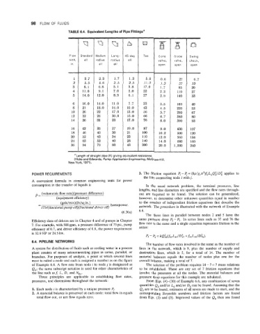
TABLE 6.4. Equivalent Lengths of Pipe Fittingsa
~~
Q Q A Q 63n
Pipe Standard Medium Long- 45-deg Tee Gate Globe Swing
radius radius ell valve, valve, check,
open open
1 2.7 2.3 1.7 1.3 5.8 0.6 27 6.7
2 5.5 4.6 3.5 2.5 11.0 1.2 57 13
3 8.1 6.8 5.1 3.8 17.0 1.7 85 20
4 11.0 9.1 7.0 5.0 22 2.3 110 27
5 14.0 12.0 8.9 6.1 27 2.9 140 33
6 16.0 14.0 11.0 7.7 33 3.5 160 40
8 21 18.0 14.0 10.0 43 4.5 220 53
10 26 22 17.0 13.0 56 5.7 290 67
12 32 26 20.0 15.0 66 6.7 340 80
14 36 31 23 17.0 76 8.0 390 93
16 42 35 27 19.0 87 9.0 430 107
18 46 40 30 21 100 10.2 500 120
20 52 43 34 23 110 12.0 560 134
24 63 53 40 28 140 14.0 680 160
36 94 79 60 43 200 20.0 1,000 240
a Length of straight pipe (ft) giving equivalent resistance.
(Hicks and Edwards, Pump Application Engineering, McGraw-Hill,
New York, 1971).
PO WE R REQUl RE M E NTS 3. The friction equation e. - 4 = (Sp/gcnz)~jLijQ~/D~ applies to
the line connecting node i with j.
A convenient formula in common engineering units for power
consumption in the transfer of liquids is In the usual network problem, the terminal pressures, line
lengths, and line diameters are specified and the flow rates through-
p= (volumetric flow rate)(pressure difference) out are required to be found. The solution can be generalized,
(equipment efficiency) however, to determine other unknown quantities equal in number
to the number of independent friction equations that describe the
-
- (gals/min)(lb/sq in.) horsepower.
1714(fractional pump eff)(fractional driver eff) network. The procedure is illustrated with the network of Example
(6.30a) 6.6.
The three lines in parallel between nodes 2 and 5 have the
Efficiency data of drivers are in Chapter 4 and of pumps in Chapter same pressure drop Pz - Ps. In series lines such as 37 and 76 the
7. For example, with 500 gpm, a pressure difference of 75 psi, pump flow rate is the same and a single equation represents friction in the
efficiency of 0.7, and driver efficiency of 0.9, the power requirement series:
is 32.9 HP or 24.5 kw.
6.4. PIPELINE NETWORKS
The number of flow rates involved is the same as the number of
A system for distribution of fluids such as cooling water in a process lines in the network, which is 9, plus the number of supply and
plant consists of many interconnecting pipes in series, parallel, or destination lines, which is 5, for a total of 14. The number of
branches. For purposes of analysis, a point at which several lines material balances equals the number of nodes plus one for the
meet is called a node and each is assigned a number as on the figure overall balance, making a total of 7.
of Example 6.6. A flow rate from node i to node j is designated as The solution of the problem requires 14 - 7 = 7 more relations
Q,; the same subscript notation is used for other characteristics of to be established. These are any set of 7 friction equations that
the line such as f, L, D, and NRe. involve the pressures at all the nodes. The material balances and
Three principles are applicable to establishing flow rates, pressure drop equations for this example are tabulated.
pressures, and dimensions throughout the network: From Eqs. (4)-(IO) of Example 6.6, any combination of seven
quantities Q, and/or L, and/or Dij can be found. Assuming that the
1. Each node i is characterized by a unique pressure 5. Q, are to be found, estimates of all seven are made to start, and the
2. A material balance is preserved at each node: total flow in equals corresponding Reynolds numbers and friction factors are found
total flow out, or net flow equals zero. from Eqs. (2) and (3). Improved values of the Q, then are found