
Page 129 - Chemical Process Equipment - Selection and Design
P. 129
6.6. NON-NEWTONIAN LIQUIDS 101
f
AP
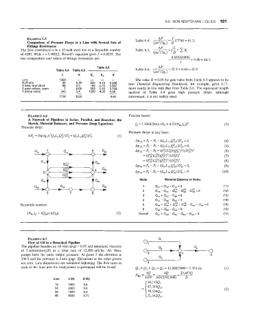
EXAMPLE 6.5 Table 6.4, -=-(1738)=61.3,
Comparison of Pressure Drops in a Line with Several Sets of (Pu2/2gc) D
fittings Resistances AP L
The flow considered is in a 12-inch steel Bine at a Reynolds number Table 6.5, -- -f-+c K,
of 60080. With E = 0.00015, Round's equation gives f = 0.0353. The (PU2/2&) D
line composition and values of fittings resistances are:
Table 6.6 Table 6.6, ~- -35.3+8.64=43.9.
(Pu2/2gc)
L K Kl K2 K
I .,.,"
I inn i nnn - -- - The value K = 0.05 for gate valve from Table 6.5 appears to be
i'Gi ells 20 0.25 500 0.15 0.246 low: Chemical Engineering Handbook, for example, gives 0.17,
4 tees, branched 66 0.5 150 0.15 0.567
2 gate valves, open 7 0.05 300 0.10 0.158 more nearly in line with that from Table 6.6. The equivalent length
5.4
340
1 glabe valve - - 1500 4.00 4.58
- method of Table 6.4 gives high pressure drops; although
1738 9.00 8.64 convenient, it is not widely used.
EXAMPLE 6.6
A Network of Pipelines in Series, Parallel, and Branches: the
Sketch, Material Balances, and Pressure Drop Equations (3)
Pressure drop:
3 7 6
EXAMPLE 6.7 Q,
Flow of (Dil in a Branched Pipeline 0, 1
The pipeline handles an oil with sp gr = 0.92 and kinematic viscosity
of Scentistokes(cS) at a total rate of 12,00Ocuft/hr. All three
pumps have the same output pressure. At point 5 the elevation is
100 ft and the pressure is 2 atm gage. Elevations at the other points
are zero. Line dimensions are tabulated following. The flow rates in
each of the lines and the total power requirement will be found. Q, + Q, + Q3 = Q4 = 12,000/3600 = 3.333 C~S
N --= 4Q 4Q =- 23,657Q
Line L(ft1 D(ft1 Re - JGDV xD(5/92,900) D
'I 4 1000 0.4
24 2000 0.5
:34 1500 0.3
4000 0.75
1%