
Page 223 - Chemical process engineering design and economics
P. 223
206 Chapter 5
iDrffuser
Impeller
Shaft
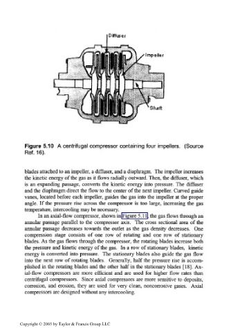
Figure 5.10 A centrifugal compressor containing four impellers. (Source
Ref. 16).
blades attached to an impeller, a diffuser, and a diaphragm. The impeller increases
the kinetic energy of the gas as it flows radially outward. Then, the diffuser, which
is an expanding passage, converts the kinetic energy into pressure. The diffuser
and the diaphragm direct the flow to the center of the next impeller. Curved guide
vanes, located before each impeller, guides the gas into the impeller at the proper
angle. If the pressure rise across the compressor is too large, increasing the gas
temperature, intercooling may be necessary.
In an axial-flow compressor, shown in Figure 5.11, the gas flows through an
annular passage parallel to the compressor axis. The cross sectional area of the
annular passage decreases towards the outlet as the gas density decreases. One
compression stage consists of one row of rotating and one row of stationary
blades. As the gas flows through the compressor, the rotating blades increase both
the pressure and kinetic energy of the gas. In a row of stationary blades, kinetic
energy is converted into pressure. The stationary blades also guide the gas flow
into the next row of rotating blades. Generally, half the pressure rise is accom-
plished in the rotating blades and the other half in the stationary blades [18]. Ax-
ial-flow compressors are more efficient and are used for higher flow rates than
centrifugal compressors. Since axial compressors are more sensitive to deposits,
corrosion, and erosion, they are used for very clean, noncorrosive gases. Axial
compressors are designed without any intercooling.
Copyright © 2003 by Taylor & Francis Group LLC