
Page 221 - Chemical process engineering design and economics
P. 221
204 Chapter 5
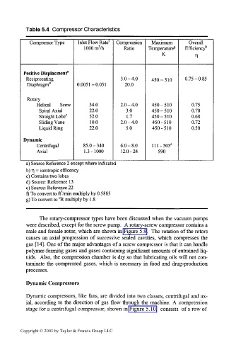
Table 5.4 Compressor Characteristics
Compressor Type Inlet Flow Rate' Compression Maximum Overall
lOOOrrrVh Ratio Temperature 8 Efficiency b
K Tl
Positive Displacment*
Reciprocating 3.0-4.0 450-510 0.75-0.85
Diaphragm d 0.0051-0.051 20.0
Rotary
Helical Scew 34.0 2.0-4.0 450-510 0.75
Spiral Axial 22.0 3.0 450-510 0.70
Straight Lobe c 52.0 1.7 450-510 0.68
Sliding Vane 10.0 2.0-4.0 450-510 0.72
Liquid Ring 22.0 5.0 450-510 0.50
Dynamic
Centrifugal 85.0 - 340 6.0-8.0 lll-505 e
Axial 1.3-1000 12.0-24 590
a) Source Reference 2 except where indicated
b) T] = isentropic efficency
c) Contains two lobes
d) Source: Reference 13
e) Source: Reference 22
f) To convert to ftVmin multiply by 0.5885
g) To convert to °R multiply by 1.8.
The rotary-compressor types have been discussed when the vacuum pumps
were described, except for the screw pump. A rotary-screw compressor contains a
male and female rotor, which are shown in Figure 5.9. The rotation of the rotors
causes an axial progression of successive sealed cavities, which compresses the
gas [14]. One of the major advantages of a screw compressor is that it can handle
polymer-forming gases and gases containing significant amounts of entrained liq-
uids. Also, the compression chamber is dry so that lubricating oils will not con-
taminate the compressed gases, which is necessary in food and drug-production
processes.
Dynamic Compressors
Dynamic compressors, like fans, are divided into two classes, centrifugal and ax-
ial, according to the direction of gas flow through the machine. A compression
stage for a centrifugal compressor, shown in Figure 5.10, consists of a row of
Copyright © 2003 by Taylor & Francis Group LLC