
Page 291 - Chemical process engineering design and economics
P. 291
270 Chapter 6
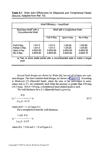
Table 6.1 Weld Joint Efficiencies for Ellipsoidal and Torispherical Heads
(Source: Adapted from Ref. 10).
Weld Efficiency - Head/Shell
3
Seamless Shell with a Shell with a Longitudinal Weld
Circumferential Weld
Full X-Ray Spot X-Ray No X-Ray
Full X-Ray 1.0/1.0 1.0/1.0 1.0/0.85 1.0/0.85
Partial X-Ray 1.0/1.0 1.0/1.0 1.0/0.85 1.0/0.85
Spot X-Ray 0.85/0.85 0.85/0.85 0.85/0.85 0.85/0.85
No X-Ray 0.80/0.80 0.85/0.85 0.85/0.85 0.80/0.70
a) Two or more shells joined with a circumferential weld to make a longer
shell
Several head designs are shown by Walas [6], but not all of these are com-
mon designs. The most common head designs are shown in Figure 6.1. According
to Markovitz [7] ellipsoidal heads, where the ratio of the semi-major to semi-
minor axis is 2:1, are commonly used when the pressure is greater than 150 psig
(10.3 barg). Below 150 psig, a torispherical head (dished head) is used.
The wall thickness for a 2:1 ellipsoidal head is given by
PD
(6.7)
2 e H S - 0.2 P
where H/D = % in Figure 6.1.
For a torispherical head the wall thickness,
1.104 PD
(6.8)
2 s H S - 0.2 P
where R/L = 0.06 and L = D in Figure 6.1.
Copyright © 2003 by Taylor & Francis Group LLC