
Page 294 - Chemical process engineering design and economics
P. 294
Separator Design 273
Table 6.3 Continued
Variables
P, ts, t H, a s, a H
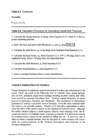
Table 6.4 Calculation Procedure for Calculating Vessel Wall Thickness
1. Calculate the design pressure, P (psig), from Equation 6.3.1 where P is the ex-
0
pected operating pressure.
2. Select the shell and head weld efficiencies, ES and £H> from Table 6.1.
3. Calculate the shell factor, cc, in the hoop stress formulas from Equation 6.3.2.
s
4. Calculate the head factor, CC H, from Equation 6.3.3. If P < 150 psig, select a tor-
rispherical head. Above 150 psig select an ellipsoidal head.
5. Calculate the shell thickness, ts, from Equation 6.3.4.
6. Calculate head thickness, t H, from Equation 6.3.5.
7. Select a standard thickness from a vessel manufacturer.
VORTEX FORMATION IN VESSELS
Vortex formation in separators must be prevented to reduce gas entrainment in the
liquid, which can result in the following: loss of valuable vapor, pump damage,
loss of flow, erroneous liquid level readings resulting in poor control, and vibra-
tions caused by unsteady two-phase flow. Vortexes appear frequently in nature
such as in hurricanes, tornados, and whirlpools. The mechanism of atmospheric
generated of vortices is an active area of research. Even the more common bath-
tub vortex is of scientific interest. Sibulkin [15] describes experiments to deter-
mine the effect of the earth's rotation on the rotation of a bathtub vortex. Although
the earth's rotation induces a small angular velocity when draining water, the di-
rection of rotation of a bathtub vortex is usually accidental. It is determined mainly
by residual motion caused by the method of filling the tub. If, however, care is
taken to reduce residual motions, then the direction of vortex rotation will consis-
tently be counterclockwise in the Northern Hemisphere and clockwise in the
Southern Hemisphere.
Copyright © 2003 by Taylor & Francis Group LLC