
Page 306 - Chemical process engineering design and economics
P. 306
Separator Design 285
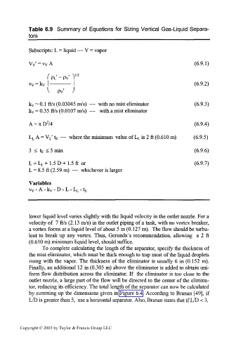
Table 6.9 Summary of Equations for Sizing Vertical Gas-Liquid Separa-
tors ______________________________________
Subscripts: L = liquid — V = vapor
V v '=v v A (6.9.1)
(6.9.2)
k v = 0. 1 ft/s (0.03045 m/s) — with no mist eliminator (6.9.3)
k v = 0.35 ft/s (0.0107 m/s) — with a mist eliminator
2
A = TI D /4 (6.9.4)
— where the minimum value of L L is 2 ft (0.610 m) (6.9.5)
L L A = V L' t s
3 < ts < 5 min (6.9.6)
L = L L +1.5D+1.5ft or (6.9.7)
L = 8.5 ft (2.59 m) — whichever is larger
Variables
v v - A - k v - D - L - L L - ts
lower liquid level varies slightly with the liquid velocity in the outlet nozzle. For a
velocity of 7 ft/s (2.13 m/s) in the outlet piping of a tank, with no vortex breaker,
a vortex forms at a liquid level of about 5 in (0.127 m). The flow should be turbu-
lent to break up any vortex. Thus, Gerunda's recommendation, allowing a 2 ft
(0.610 m) minimum liquid level, should suffice.
To complete calculating the length of the separator, specify the thickness of
the mist eliminator, which must be thick enough to trap most of the liquid droplets
rising with the vapor. The thickness of the eliminator is usually 6 in (0.152 m).
Finally, an additional 12 in (0.305 m) above the eliminator is added to obtain uni-
form flow distribution across the eliminator. If the eliminator is too close to the
outlet nozzle, a large part of the flow will be directed to the center of the elimina-
tor, reducing its efficiency. The total length of the separator can now be calculated
by summing up the dimensions given in Figure 6.4. According to Branan [49], if
L/D is greater than 5, use a horizontal separator. Also, Branan states that if L/D < 3,
Copyright © 2003 by Taylor & Francis Group LLC