
Page 307 - Chemical process engineering design and economics
P. 307
286 Chapter 6
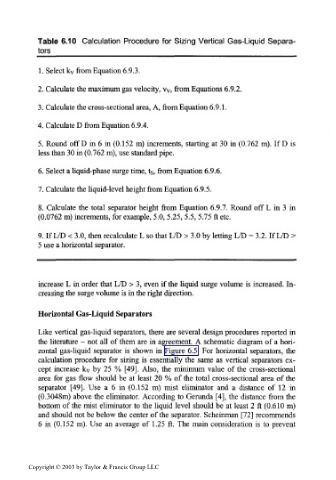
Table 6.10 Calculation Procedure for Sizing Vertical Gas-Liquid Separa-
tors______________________________________
1. Select k v from Equation 6.9.3.
2. Calculate the maximum gas velocity, vy, from Equations 6.9.2.
3. Calculate the cross-sectional area, A, from Equation 6.9.1.
4. Calculate D from Equation 6.9.4.
5. Round off D in 6 in (0.152 m) increments, starting at 30 in (0.762 m). If D is
less than 30 in (0.762 m), use standard pipe.
6. Select a liquid-phase surge time, ts, from Equation 6.9.6.
7. Calculate the liquid-level height from Equation 6.9.5.
8. Calculate the total separator height from Equation 6.9.7. Round off L in 3 in
(0.0762 m) increments, for example, 5.0, 5.25, 5.5, 5.75 ft etc.
9. If L/D < 3.0, then recalculate L so that L/D > 3.0 by letting L/D = 3.2. If L/D >
5 use a horizontal separator.
increase L in order that L/D > 3, even if the liquid surge volume is increased. In-
creasing the surge volume is in the right direction.
Horizontal Gas-Liquid Separators
Like vertical gas-liquid separators, there are several design procedures reported in
the literature - not all of them are in agreement. A schematic diagram of a hori-
zontal gas-liquid separator is shown in Figure 6.5. For horizontal separators, the
calculation procedure for sizing is essentially the same as vertical separators ex-
cept increase k v by 25 % [49]. Also, the minimum value of the cross-sectional
area for gas flow should be at least 20 % of the total cross-sectional area of the
separator [49]. Use a 6 in (0.152 m) mist eliminator and a distance of 12 in
(0.3048m) above the eliminator. According to Gerunda [4], the distance from the
bottom of the mist eliminator to the liquid level should be at least 2 ft (0.610 m)
and should not be below the center of the separator. Scheinman [72] recommends
6 in (0.152 m). Use an average of 1.25 ft. The main consideration is to prevent
Copyright © 2003 by Taylor & Francis Group LLC