
Page 344 - Chemical process engineering design and economics
P. 344
Separator Design 323
the height of a packed column from Equation 6.21.7P.
The calculation procedure in Table 6.22 could also be used for a multi-
component mixture. After calculating the number of stages for separating the key
component from the mixture, then the composition of all other components in the
exit stream can be calculated using the Kremser equation, Equation 6.21.5A for
absorbers or 6.21.5S for strippers.
The tray spacing, Z T, calculated from Equation 6.21.9T, depends on the pres-
sure [75]. To obtain HETS from Equation 6.21.9P requires the column diameter.
To obtain the column diameter, calculate the maximum allowable gas velocity to
prevent entrainment of liquid. First, find the maximum value of the parameter k,
from Equation 6.23.4 in Table 6.23, which occurs when the column is about to
flood. The column is then designed to operate below the flood point. The maxi-
mum value of k is found in Figure 6.18 for trays. Fair [52] recommends that the
flooding parameter, obtained from Figure 6.18 for tray columns, be multiplied by
0.9 for nonfoaming liquids. Treybal [29] recommends 0.75 for foaming liquids. In
Figure 6.18, the flooding parameter requires correcting for surface tension and tray
geometry using corrections given by Fair [52]. Figure 6.18 was developed by Fair
[52] for fractionators. Henley and Seader [65] used an earlier version of Figure
6.18 for absorbers and strippers. Fair [52] lists restrictions on Equation 6.23.5 for
tray columns. He also corrects k for tray geometry, but for preliminary estimates
we want to avoid designing trays.
If the column diameter > 2.5 ft (0.762 m), use a tray column. Because of
maintenance, a tray column has to be internally accessible [75, 31]. The minimum
diameter column that is accessible is 2.5 ft. For packed columns, Figure 6.19 only
gives factors for a limited number of packings. For other packings use the flooding
ratios in Table 6.26. To obtain k for a packing listed in Table 6.26 multiply the
flooding ratio by the flooding factor for 50 mm (2 in) Pall rings obtained from
Figure 6.19. For packed columns use 0.7 for nonfoaming liquids, a commonly
accepted value, and 0.4 for foaming liquids [6]. After obtaining k v, the column
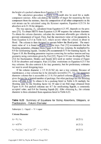
diameter is then calculated from equations listed in Table 6.23.
Table 6.23 Summary of Equations for Sizing Absorbers, Strippers, or
Fractionators - Column Diameter______________________
Subscripts: L = liquid — V = vapor
Column Diameter
A = VV'/V V (6.23.1)
2
A = 7iD /4 (6.23.2)
v v = k v [ (PL' - Pv') / Pv' l" 2 " v s = 0.9 v v (6.23.3)
Copyright © 2003 by Taylor & Francis Group LLC