
Page 466 - Chemical process engineering design and economics
P. 466
Design of Flow Systems 445
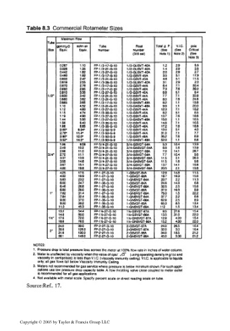
Table 8.3 Commercial Rotameter Sizes
Maximum Flow
Tube
gpmHzO scfm air Tube Float Tolal a P V.I.C. psia
Size Equiv. Equiv. Number Number (See (See Critical
(31 6 ss!) Notel) Note 2) (See
Note 3)
0.267 1.10 FP-1/2-17-G-10 1 /2-GUSVT-40A 1.2 2.9 5.5
0.328 1.35 FP-1/2-21-G-10 1 /2-GUSVT-40A 1.4 2.9 3.5
0.442 1.82 FP-1/2-27-Q-10 1 /2-GUSVT-40A 2.0 2.9 2.7
0.480 1.92 FP-1/2-17-G-10 1 /2-GSVT-45A 3.5 5.1 17.9
0.600 2.47 FP-1/2-21-G-10 1 /2-GSVT-45A 4.6 5.1 11.5
0.619 2.55 FP-1/2-35-G-10 1 /2-GUSVT-40A 3.1 2.9 2.0
0.670 2.76 FP-1/2-17-G-10 1 /2-GSVT-44A 6.4 7.1 33.4
0.690 2.85 FP-1/2-17-G-H) 1 /2-GSVT-48A 7.3 7.6 39.0
0.810 3.35 FP-1/2-27-G-10 1 /2-GSVT-45A 6.8 5.1 8.4
1/2" 0.830 3.42 FP-1/2-21-G-10 1 /2-GSVT-44A 7.7 7.1 33.8
0.880 3.62 FP-1/2-21-G-10 1 /2-GSVT-48A 8.0 7.6 24.6
0.885 3.65 FP-1/2-17-G-10 1 /2-GNSVT-48A 8.2 1.1 19.8
1.10 4.52 FP-1/2-21-G-10 1 /2-GNSVT-48A 9.9 1.1 20.0
1.12 4.60 FP-1/2-27-G-10 1 /2-GSVT-44A 12.3 7.1 162
1.15 4.74 FP-1/2-35-G-10 1 /2-GSVT-45A 8.2 5.1 8.5
1.19 4.90 FP-1/2-27-G-10 1 /2-GSVT-48A 13.7 7.6 18.6
1.44 5.93 FP-1/2-27-G-10 1 /2-GNSVT-48A 15.8 1.1 165
1.56 6.43 FP-1/2-35-G-10 1 /2-GSVT-44A 14.8 7.1 16.5
1.66 6.85 FP-1/2-35-G-10 1 /2-GSVT-48A 172 7.6 18.8
2.00< 8.24' FP-1 /2-50-G-9 1 /2-GSVT-45A 12.0 5.1 4.0
2.78' 11.4" FP-1 /2-50-G-9 1 /2-GSVT-44A 31.0 7.1 7.7
2.90* 12.0- FP-1 /2-50-G-9 1 /2-GSVT-48A 35.2 7.6 8.9
3.52' 14.5* FP-1 /2-50-G-9 1 /2-GNSVT-48A 52.0 1.1 8.8
1.96 8.08 FP-3/4-21-G-10 3/4-GSVGT-54A 5.3 10.4 13.9
2.49 10.2 FP-3/4-21-G-10 3/4-GNSVGT-54A 6.8 1.6 13.9
2.66 11.0 FP-3/4-21-G-10 3/4-GSVGT-59A 7.0 14.1 28.7
3/4" 2.70 11.1 FP-3/4-27-G-10 3/4-GSVGT-54A 7.7 10.4 9.6
3.37 13.9 FP-3/4-21-G-10 3/4-GNSVGT-59A 11.5 2.1 263
3.55 14.6 FP-3/4-27-G-10 3/4-GNSVGT-54A 11.5 1.6 9.6
3.67 15.1 FP-3M-27-G-10 3/4-GSVGT-59A 13.7 14.1 19.8
4.80 19.8 FP-3/4-27-G-10 3/4-GNSVGT-59A 20.5 2.1 19.8
4.25 17.5 FP-1-27-G-10 1-GSVGT-64A 12.9 14.8 11.5
4.82 19.9 FP-1-27-G-10 1-GSVGT-68A 18.7 16.9 15.6
5.63 23.2 FP-1-27-G-10 1-GNSVGT-64A 20.7 2.2 11.3
6.00 24.7 FP-1-35-G-10 1-GSVGT-64A 24.6 14.8 6.8
6.46 26.6 FP-1-27-G-10 1-GNSVGT-68A 32.5 2.5 15.6
6.80 28.0 FP-1-35-G-10 1-GSVGT-68A 37.0 16.9 8.9
1" 7.62 31.4 FP-1-27-G-10 1-GNSVGT-69A 75.0 1.5 22.2
7.84 32.4 FP-1-35-G-10 1-GNSVGT-64A 37.7 22 68
9.00 37.0 FP-1-35-G-10 1-GNSVGT-68A 628 2.5 8.9
950 39.2 FP-1-35-G-10 1-GSVGT-69A 65.3 8.5 13.4
11.0 45.3 FP-1-35-G-10 1-GNSVGT-69A 112 1.5 13.4
13.2 54.4 FP-114-27-G-10 1V4-GSVGT-87A 9.5 27.6 15.4
14.6 60.0 FP-1V4-27-G-10 1V4-GSVGT-86A 13.5 31.0 22.0
114" 17.6 72.0 FP-1VS-27-G-10 1V4-GNSVGT-87A 12.8 4.20 15.4
18.6 76.5 FP-1V4-27-G-10 1Vi-GNSVGT-86A 15.2 4.80 22.0
24.0 99.0 FP-2-27-G-10 2-GSVGT-97A 24.0 26.5 16.4
30.6 126.0 FP-2-27-G-10 2-GNSVGT-97A 32.0 3.0 16.4
2"
31.6 130.0 FP-2-27-G-10 2-GSVGT-98A 34.0 18.5 212
36.1 149:0 FP-2-27-G-10 2-GNSVGT-98A 45.0 3.30 212
NOTES:
1. Pressure drop is total pressure loss across the meter al 100% flow rate in inches of water column.
2. Meter is unaffected by viscosity when the value of cos/ /!o~ (usingoperatingdensitying/ccand
viscosity in centipoises) is less than V.I.C. (viscosity immunity ceiling). V.I.C. is applicable to liquids
only; all gas flows fall below Viscosity Immunity Ceiling.
3. Meters not recommended for gas service where pressure is below minimum shown. For such appli-
cations use low pressure drop capacity table. A flow throttling valve close coupled to meter outlet
is recommended for all gas applications.
4. Not available with metal scale. Specify percent scale or direct reading scale on tube.
Source:Ref.. 17.
Copyright © 2003 by Taylor & Francis Group LLC