
Page 14 - Circuit Analysis II with MATLAB Applications
P. 14
Chapter 1 Second Order Circuits
1.2 The Series RLC Circuit with DC Excitation
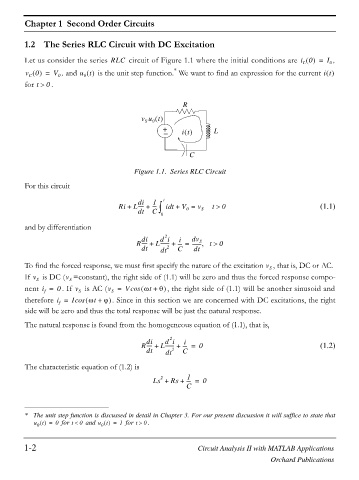
Let us consider the series RLC circuit of Figure 1.1 where the initial conditions are i 0 = I 0 ,
L
*
v 0 = V 0 , and u t is the unit step function. We want to find an expression for the current it
C
0
for t ! . 0
R
v u t
S
0
+ L
it `
C
Figure 1.1. Series RLC Circuit
For this circuit
di 1 t
Ri + L----- + ---- ³ it + V = v t ! 0 (1.1)
d
dt C 0 S
0
and by differentiation
2
di d i i dv
S
R----- + L------- + ---- = -------- t ! 0
dt dt 2 C dt
To find the forced response, we must first specify the nature of the excitation , that is, DC or AC.
v
S
v
If v S is DC ( =constant), the right side of (1.1) will be zero and thus the forced response compo-
S
nent i = 0 . If v S is AC (v = Vcos Zt + T , the right side of (1.1) will be another sinusoid and
f
S
therefore i = Icos Zt + M . Since in this section we are concerned with DC excitations, the right
f
side will be zero and thus the total response will be just the natural response.
The natural response is found from the homogeneous equation of (1.1), that is,
2
di d i i
R----- + L------- + ---- = 0 (1.2)
dt dt 2 C
The characteristic equation of (1.2) is
1
2
Ls + Rs + ---- = 0
C
* The unit step function is discussed in detail in Chapter 3. For our present discussion it will suffice to state that
u t = 0 for t 0 and u t = 1 for t ! . 0
0
0
1-2 Circuit Analysis II with MATLAB Applications
Orchard Publications