
Page 144 - Civil Engineering Formulas
P. 144
84 CHAPTER THREE
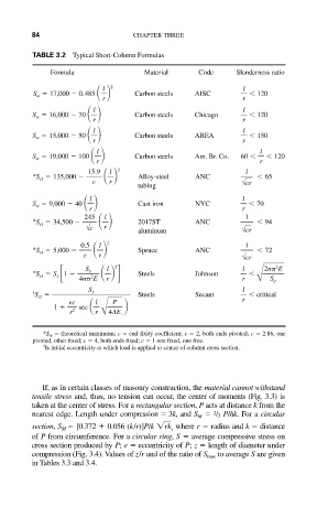
TABLE 3.2 Typical Short-Column Formulas
Formula Material Code Slenderness ratio
2 l
l
S w 17,000 0.485 Carbon steels AISC 120
r r
l
l
S w 16,000 70 Carbon steels Chicago 120
r r
l
l
S w 15,000 50 r Carbon steels AREA r 150
l
l
S w 19,000 100 Carbon steels Am. Br. Co. 60 120
r r
15.9 l 2 l
*S cr 135,000 Alloy-steel ANC 65
c r wcr
tubing
l
l
S w 9,000 40 Cast iron NYC 70
r r
245 1
l
*S cr 34,500 2017ST ANC 94
wc r
aluminum wcr
0.5 2 1
l
*S cr 5,000 Spruce ANC 72
c r wcr
*S cr S y 1 S y 2 Steels Johnson l 2n
E
2
2
l
4n
E r r B S y
l
† S cr S y Steels Secant critical
ec l P r
1 sec
r 2 r B4AE
*S cr theoretical maximum; c end fixity coefficient; c 2, both ends pivoted; c 2.86, one
pivoted, other fixed; c 4, both ends fixed; c 1 one fixed, one free.
†
Is initial eccentricity at which load is applied to center of column cross section.
If, as in certain classes of masonry construction, the material cannot withstand
tensile stress and, thus, no tension can occur, the center of moments (Fig. 3.3) is
taken at the center of stress. For a rectangular section, P acts at distance k from the
nearest edge. Length under compression 3k, and S M /3 P/hk. For a circular
2
section, S M [0.372 0.056 (k/r)]P/k rk , where r radius and k distance
of P from circumference. For a circular ring, S average compressive stress on
cross section produced by P; e eccentricity of P; z length of diameter under
compression (Fig. 3.4). Values of z/r and of the ratio of S max to average S are given
in Tables 3.3 and 3.4.