
Page 182 - Civil Engineering Formulas
P. 182
CONCRETE FORMULAS 119
Cross section of beam Stress diagram
f c
C = 1 2 f c kbd
kd
d
jd
A s
T = A f = f pbd
s
s s
f /n
s
b
2
M = 1 f kjbd = f pjbd 2
2 c s
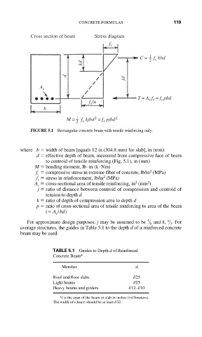
FIGURE 5.1 Rectangular concrete beam with tensile reinforcing only.
where b width of beam [equals 12 in (304.8 mm) for slab], in (mm)
d effective depth of beam, measured from compressive face of beam
to centroid of tensile reinforcing (Fig. 5.1), in (mm)
M bending moment, lb . in (k . Nm)
2
f compressive stress in extreme fiber of concrete, lb/in (MPa)
c
2
f stress in reinforcement, lb/in (MPa)
s
2
2
A cross-sectional area of tensile reinforcing, in (mm )
s
j ratio of distance between centroid of compression and centroid of
tension to depth d
k ratio of depth of compression area to depth d
p ratio of cross-sectional area of tensile reinforcing to area of the beam
( A /bd)
s
7 1
For approximate design purposes, j may be assumed to be 8 and k, 3 . For
average structures, the guides in Table 5.1 to the depth d of a reinforced concrete
beam may be used.
TABLE 5.1 Guides to Depth d of Reinforced
Concrete Beam*
Member d
Roof and floor slabs l/25
Light beams l/15
Heavy beams and girders l/12–l/10
*l is the span of the beam or slab in inches (millimeters).
The width of a beam should be at least l/32.