
Page 183 - Civil Engineering Formulas
P. 183
120 CHAPTER FIVE
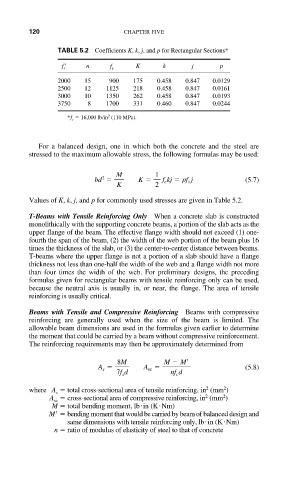
TABLE 5.2 Coefficients K, k, j, and p for Rectangular Sections*
f s n f s K k j p
2000 15 900 175 0.458 0.847 0.0129
2500 12 1125 218 0.458 0.847 0.0161
3000 10 1350 262 0.458 0.847 0.0193
3750 8 1700 331 0.460 0.847 0.0244
2
*f s 16,000 lb/in (110 MPa).
For a balanced design, one in which both the concrete and the steel are
stressed to the maximum allowable stress, the following formulas may be used:
M 1
bd K f e kj pf s j (5.7)
2
K 2
Values of K, k, j, and p for commonly used stresses are given in Table 5.2.
T-Beams with Tensile Reinforcing Only When a concrete slab is constructed
monolithically with the supporting concrete beams, a portion of the slab acts as the
upper flange of the beam. The effective flange width should not exceed (1) one-
fourth the span of the beam, (2) the width of the web portion of the beam plus 16
times the thickness of the slab, or (3) the center-to-center distance between beams.
T-beams where the upper flange is not a portion of a slab should have a flange
thickness not less than one-half the width of the web and a flange width not more
than four times the width of the web. For preliminary designs, the preceding
formulas given for rectangular beams with tensile reinforcing only can be used,
because the neutral axis is usually in, or near, the flange. The area of tensile
reinforcing is usually critical.
Beams with Tensile and Compressive Reinforcing Beams with compressive
reinforcing are generally used when the size of the beam is limited. The
allowable beam dimensions are used in the formulas given earlier to determine
the moment that could be carried by a beam without compressive reinforcement.
The reinforcing requirements may then be approximately determined from
8M M M
A s A sc (5.8)
7f s d nf c d
2
2
where A total cross-sectional area of tensile reinforcing, in (mm )
s
2
2
A cross-sectional area of compressive reinforcing, in (mm )
sc
M total bending moment, lb in (K Nm)
M bending moment that would be carried by beam of balanced design and
same dimensions with tensile reinforcing only, lb in (K Nm)
n ratio of modulus of elasticity of steel to that of concrete