
Page 184 - Civil Engineering Formulas
P. 184
CONCRETE FORMULAS 121
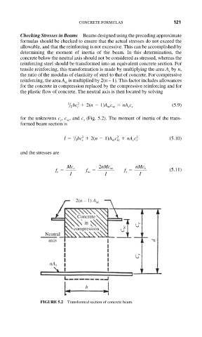
Checking Stresses in Beams Beams designed using the preceding approximate
formulas should be checked to ensure that the actual stresses do not exceed the
allowable, and that the reinforcing is not excessive. This can be accomplished by
determining the moment of inertia of the beam. In this determination, the
concrete below the neutral axis should not be considered as stressed, whereas the
reinforcing steel should be transformed into an equivalent concrete section. For
tensile reinforcing, this transformation is made by multiplying the area A by n,
s
the ratio of the modulus of elasticity of steel to that of concrete. For compressive
reinforcing, the area A is multiplied by 2(n – 1). This factor includes allowances
sc
for the concrete in compression replaced by the compressive reinforcing and for
the plastic flow of concrete. The neutral axis is then located by solving
1 2 (5.9)
2 bc c 2(n 1)A sc c sc nA s c s
for the unknowns c , c , and c (Fig. 5.2). The moment of inertia of the trans-
c sc s
formed beam section is
1 3 2 2
I 3 bc c 2(n 1)A sc c sc nA s c s (5.10)
and the stresses are
Mc c 2nMc sc nMc s
f c f sc f s (5.11)
I I I
2(n – 1) A sc
Concrete
in C c
compression C sc
Neutral
axis d
C s
nA s
b
FIGURE 5.2 Transformed section of concrete beam.