Page 274 - Civil Engineering Formulas
P. 274

208                    CHAPTER NINE

           ALLOWABLE-STRESS DESIGN FOR
           BUILDING COLUMNS

           The AISC specification for allowable-stress design (ASD) for buildings pro-
           vides two formulas for computing allowable compressive stress  F , ksi
                                                                a
           (MPa), for main members. The formula to use depends on the relationship
           of the largest effective slenderness ratio  Kl/r of the cross section of any
           unbraced segment to a factor  C defined by the following equation and
                                    c
           Table 9.1:
                                       2
                                     2
 E   756.6
                               C c                               (9.4)
                                   B F y     F y
           where E   modulus of elasticity of steel
                    29,000 ksi (128.99 GPa)
                F   yield stress of steel, ksi (MPa)
                 y
           When Kl/r is less than C ,
                             c
                                           2
                                     1    (Kl/r) 2  F y
                              F a        2C c                    (9.5)
                                        F.S.

                                 5   3(Kl/r)  (Kl/r) 3
           where F.S.   safety factor              .
                                 3    8C c     8C c 3
           When Kl/r exceeds C , c


                                      2
                                   12
 E    150,000
                             F a                                 (9.6)
                                  23(Kl/r) 2  (Kl/r) 2
             The effective-length factor K, equal to the ratio of effective-column length
           to actual unbraced length, may be greater or less than 1.0. Theoretical K values
           for six idealized conditions, in which joint rotation and translation are either
           fully realized or nonexistent, are tabulated in Fig. 9.1.


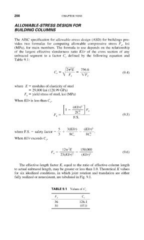
                             TABLE 9.1 Values of C c
                               F y          C c
                               36          126.1
                               50          107.0
   269   270   271   272   273   274   275   276   277   278   279