
Page 326 - Civil Engineering Formulas
P. 326
BRIDGE AND SUSPENSION-CABLE FORMULAS 259
COMPOSITE CONSTRUCTION IN HIGHWAY BRIDGES
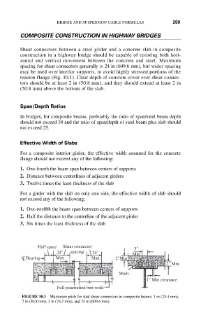
Shear connectors between a steel girder and a concrete slab in composite
construction in a highway bridge should be capable of resisting both hori-
zontal and vertical movement between the concrete and steel. Maximum
spacing for shear connectors generally is 24 in (609.6 mm), but wider spacing
may be used over interior supports, to avoid highly stressed portions of the
tension flange (Fig. 10.1). Clear depth of concrete cover over shear connec-
tors should be at least 2 in (50.8 mm), and they should extend at least 2 in
(50.8 mm) above the bottom of the slab.
Span/Depth Ratios
In bridges, for composite beams, preferably the ratio of span/steel beam depth
should not exceed 30 and the ratio of span/depth of steel beam plus slab should
not exceed 25.
Effective Width of Slabs
For a composite interior girder, the effective width assumed for the concrete
flange should not exceed any of the following:
1. One-fourth the beam span between centers of supports
2. Distance between centerlines of adjacent girders
3. Twelve times the least thickness of the slab
For a girder with the slab on only one side, the effective width of slab should
not exceed any of the following:
1. One-twelfth the beam span between centers of supports
2. Half the distance to the centerline of the adjacent girder
3. Six times the least thickness of the slab
Half space Shear connector 3"
24" spacing 24" Min
C Bearing Max Max 2"Min
L
2" Min
Studs
1" Min clearance
Full penetration butt weld
FIGURE 10.1 Maximum pitch for stud shear connectors in composite beams: 1 in (25.4 mm),
2 in (50.8 mm), 3 in (76.2 mm), and 24 in (609.6 mm).