
Page 391 - Civil Engineering Formulas
P. 391
HYDRAULICS AND WATERWORKS FORMULAS 319
where is an empirical coefficient that represents the degree of turbulence.
Experimental data indicate that may vary from about 1.03 to 1.36 for pris-
matic channels. It is, however, normally taken as 1.00 for practical hydraulic work
and is evaluated only for precise investigations of energy loss.
The total energy per pound (kilogram) of water relative to the bottom of the
channel at a vertical section is called the specific energy head H . It is com-
e
posed of the depth of flow at any point, plus the velocity head at the point. It is
expressed in feet (meter) as
V 2
H e d (12.79)
2g
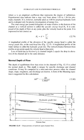
A longitudinal profile of the elevation of the specific energy head is called the
energy grade line, or the total-head line (Fig. 12.15). A longitudinal profile of the
water surface is called the hydraulic grade line. The vertical distance between these
profiles at any point equals the velocity head at that point.
Loss of head due to friction h in channel length L equals the drop in eleva-
f
tion of the channel Z in the same distance.
Normal Depth of Flow
The depth of equilibrium flow that exists in the channel of Fig. 12.15 is called
the normal depth d . This depth is unique for specific discharge and channel
n
conditions. It may be computed by a trial-and-error process when the channel
shape, slope, roughness, and discharge are known. A form of the Manning equa-
tion is suggested for this calculation:
Qn
AR 2/3 (12.80)
1.486S 1/2
1 2
V 1 2 Energy grade line S h f
2g 2 2
Hydraulic grade line V 2 V 1
S W 2g 2g
V 1
d 1
V = V 1
2
Channel bottom d = d 1
2
ΔZ S 0
Z 1
Z 2
L
Datum line
FIGURE 12.15 Characteristics of uniform open-channel flow.