
Page 428 - Civil Engineering Formulas
P. 428
354 CHAPTER TWELVE
Axis of dam
H Buttresses@15'–0"c.c.
1
18 D
2 1 17
a 16
3 2 13 14 15
4 7 3 9 10 11 12
5 6
4
5 Equipotential
lines
Flow lines
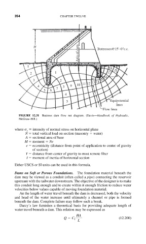
FIGURE 12.31 Buttress dam flow net diagram. (Davis—Handbook of Hydraulic,
McGraw-Hill.)
where intensity of normal stress on horizontal plane
x
N total vertical load on section (masonry water)
A sectional area of base
M moment Ne
e eccentricity (distance from point of application to center of gravity
of section)
Y distance from center of gravity to most remote fiber
I moment of inertia of horizontal section
Either USCS or SI units can be used in this formula.
Dams on Soft or Porous Foundations. The foundation material beneath the
dam may be viewed as a conduit (often called a pipe) connecting the reservoir
upstream with the tailwater downstream. The objective of the designer is to make
this conduit long enough and to create within it enough friction to reduce water
velocities below values capable of moving foundation material.
An the length of water travel beneath the dam is decreased, both the velocity
and head of the water increase until ultimately a channel or pipe is formed
beneath the dam. Complete failure may follow such a break.
Darcy’s law furnishes a theoretical basis for providing adequate length of
water travel beneath a dam. This relation may be expressed as
HA
Q C 1 (12.200)
L