
Page 457 - Civil Engineering Formulas
P. 457
STORMWATER, WASTEWATER, AND ENVIRONMENTAL PROTECTION 383
DESIGN OF AN AERATED GRIT CHAMBER
Grit removal in a wastewater treatment facility prevents unnecessary abrasion
and wear of mechanical equipment such as pumps and scrappers, and grit depo-
sition in pipelines and channels. Grit chambers are designed to remove grit
(generally characterized as non-putrescible solids) consisting of sand, gravel, or
other heavy solid materials that have settling velocities greater than those of the
organic putrescible solids in the wastewater.
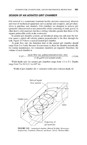
In aerated grit chamber systems, air introduced along one side near the bot-
tom causes a spiral roll velocity pattern perpendicular to the flow through the
tank. Figure 13.9 shows a typical aerated grit chamber.
At peak flow rate, the detention time in the aerated grit chamber should
range from 2 to 5 min. Because it is necessary to drain the chamber periodically
for routine maintenance, two redundant chambers are required. Therefore, the
volume of each chamber is
(peak flow rate, gal/day)(detention time, min)
3
V (ft ) (13.84)
3
(7.48 gal/ft )(24 h/d)(60 min/h)
Width-depth ratio for aerated grit chambers range from 1:1 to 5:1. Depths
range from 7 to 16 ft (2.1 to 4.87 m).
Width of grit chamber (ft) (selected width-ratio) (chosen depth, ft)
Helical liquid
flow pattern
Outlet weir
Inlet
Trajectory of
grit particles
FIGURE 13.9 Aerated grit chamber. (Metcalf & Eddy, Wastewater
Engineering: Treatment, Disposal, and Reuse, 3rd ed., McGraw-Hill.)