
Page 97 - Civil Engineering Formulas
P. 97
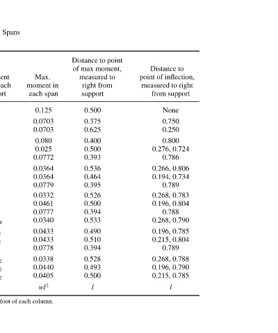
Distance to  point of inflection,  measured to right   from support  None  0.750  0.250  0.800  0.276, 0.724  0.786  0.266, 0.806  0.194, 0.734  0.789  0.268, 0.783  0.196, 0.804  0.788  0.268, 0.790  0.196, 0.785  0.215, 0.804  0.789  0.268, 0.788  0.196, 0.790  0.215, 0.


               Distance to point   of max moment,  measured to   right from  support  0.500  0.375  0.625  0.400  0.500  0.393  0.536  0.464  0.395  0.526  0.500  0.394  0.533  0.490  0.510  0.394  0.528  0.493  0.500  l


                    moment in
                  Max.  each span  0.125  0.0703  0.0703  0.080  0.025  0.0772  0.0364  0.0364  0.0779  0.0332  0.0461  0.0777  0.0340  0.0433  0.0433  0.0778  0.0338  0.0440  0.0405  wl 2


        Uniformly Loaded Continuous Beams over Equal Spans
                  Moment  over each  support  0  0  1   8  0  1   10  0  3   28  2   28  0  4   38  3   38  0  11   104  8   104  9   104  0  15   142  11   142  12   142  wl 2


          l)       R
                left,     right. reaction at     R  1   2  3   8  5   8  4   10  5   10  11   28  15   28  13   28  15   38  20   38  19   38  41   104  55   104  51   104  53   104  56   142  75   142  70   142  71   142  w l
          w; length of each span  Shear on each side  of support. L     any support is L  L  0  0  5   8  0  6   10  0  17   28  13   28  0  23   38  18   38  0  63   104  49   104  53   104  0  86   142  67   142  72   142  w l The numerical values given are coefficients of the expressio


                  R
          (Uniform load per unit length  Notation  of  support  of span  1 or 2  1  2  1  2  1  2  3  1  2  3  1  2  3  4  1  2  3  4


        TABLE 2.1  Number  of  supports  2  3  4  5  6  7  8    Values apply to


                                    50