
Page 98 - Civil Engineering Formulas
P. 98
BEAM FORMULAS 51
Shear
Moment
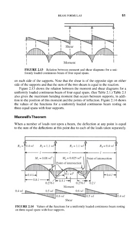
FIGURE 2.13 Relation between moment and shear diagrams for a uni-
formly loaded continuous beam of four equal spans.
on each side of the supports. Note that the shear is of the opposite sign on either
side of the supports and that the sum of the two shears is equal to the reaction.
Figure 2.13 shows the relation between the moment and shear diagrams for a
uniformly loaded continuous beam of four equal spans. (See Table 2.1.) Table 2.1
also gives the maximum bending moment that occurs between supports, in addi-
tion to the position of this moment and the points of inflection. Figure 2.14 shows
the values of the functions for a uniformly loaded continuous beam resting on
three equal spans with four supports.
Maxwell’s Theorem
When a number of loads rest upon a beam, the deflection at any point is equal
to the sum of the deflections at this point due to each of the loads taken separately.
R = 0.4 wl R = 1.1 wl R = 1.1 wl R = 0.4 wl
2
1
3
4
l l l
M = 0.08 wl 2 M = 0.025 wl 2 Point of intersection
2
1
Point of intersection
0.4 l 0.1 wl 2 0.4 l
0.8 l 0.5 l
0.276 l 0.276 l 0.2 l
Moment
0.4 wl 0.5 wl 0.6 wl
0.6 wl 0.5 wl 0.4 wl
Shear
FIGURE 2.14 Values of the functions for a uniformly loaded continuous beam resting
on three equal spans with four supports.