
Page 47 - Complementarity and Variational Inequalities in Electronics
P. 47
The Variational Inequality Problem Chapter | 3 37
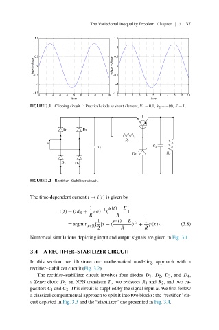
FIGURE 3.1 Clipping circuit 1: Practical diode as shunt element, V 1 = 0.1, V 2 =−90, E = 1.
FIGURE 3.2 Rectifier–Stabilizer circuit.
The time-dependent current t ø i(t) is given by
1 −1 u(t) − E
i(t) = (id R + ∂ϕ) ( )
R R
1 u(t) − E 2 1
= argmin x∈R { |x − ( )| + ϕ(x)}. (3.8)
2 R R
Numerical simulations depicting input and output signals are given in Fig. 3.1.
3.4 A RECTIFIER–STABILIZER CIRCUIT
In this section, we illustrate our mathematical modeling approach with a
rectifier–stabilizer circuit (Fig. 3.2).
The rectifier–stabilizer circuit involves four diodes D 1 , D 2 , D 3 , and D 4 ,
a Zener diode D z , an NPN transistor T , two resistors R 1 and R 2 , and two ca-
pacitors C 1 and C 2 . This circuit is supplied by the signal input u. We first follow
a classical compartmental approach to split it into two blocks: the “rectifier” cir-
cuit depicted in Fig. 3.3 and the “stabilizer” one presented in Fig. 3.4.